Edge mount connectors offer a low-profile design ideal for saving space on printed circuit boards, while through-hole connectors provide superior mechanical strength and durability due to their insertion through the PCB. Choosing between them depends on your device's space constraints and the required robustness for the connection.
Table of Comparison
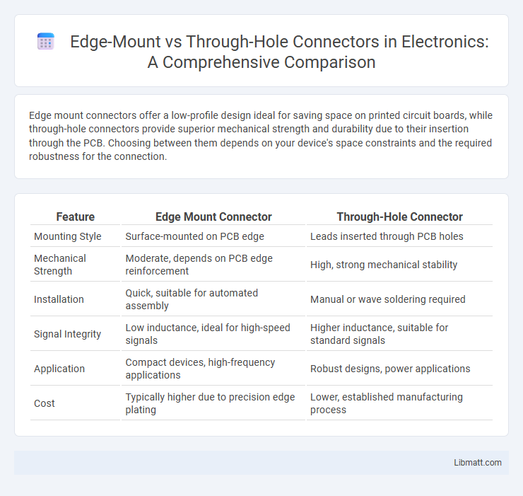
| Feature | Edge Mount Connector | Through-Hole Connector |
|---|---|---|
| Mounting Style | Surface-mounted on PCB edge | Leads inserted through PCB holes |
| Mechanical Strength | Moderate, depends on PCB edge reinforcement | High, strong mechanical stability |
| Installation | Quick, suitable for automated assembly | Manual or wave soldering required |
| Signal Integrity | Low inductance, ideal for high-speed signals | Higher inductance, suitable for standard signals |
| Application | Compact devices, high-frequency applications | Robust designs, power applications |
| Cost | Typically higher due to precision edge plating | Lower, established manufacturing process |
Introduction to Connector Mounting Techniques
Edge mount connectors attach directly to the edge of a printed circuit board (PCB), offering easy access for high-density applications and efficient signal transmission. Through-hole connectors use pins inserted through drilled holes on the PCB, providing strong mechanical bonds ideal for heavy or high-vibration environments. Both techniques influence assembly methods, reliability, and design considerations in electronic device manufacturing.
What is an Edge Mount Connector?
An edge mount connector is designed to attach directly to the edge of a printed circuit board (PCB), providing a reliable interface for signal transmission without the need for extended pins. It offers compact, space-saving connectivity by aligning the connector with the PCB edge, ideal for applications requiring high-density connections. Your choice of an edge mount connector ensures streamlined installation and efficient electrical performance in modern electronic assemblies.
What is a Through-Hole Connector?
A Through-Hole Connector is an electronic component designed to be mounted by inserting its leads through pre-drilled holes on a printed circuit board (PCB) and soldered for strong mechanical and electrical connections. This mounting method offers enhanced durability and is ideal for applications subjected to mechanical stress or high power. Choosing the right connector type affects your device's reliability and assembly process efficiency.
Key Differences Between Edge Mount and Through-Hole Connectors
Edge mount connectors are designed to slide onto the edge of a printed circuit board (PCB), providing a compact and space-saving connection ideal for high-density applications. Through-hole connectors require pins to be inserted into drilled holes on the PCB, offering robust mechanical strength and enhanced durability suitable for environments with mechanical stress. The choice between edge mount and through-hole connectors depends on factors such as assembly complexity, board space constraints, and mechanical requirements.
Electrical Performance Comparison
Edge mount connectors offer superior signal integrity and reduced insertion loss due to their shorter signal paths and low-inductance design, making them ideal for high-frequency applications. Through-hole connectors provide robust mechanical stability and better resistance to vibration, but may introduce higher parasitic capacitance and inductance that can affect electrical performance. Your choice should consider the balance between electrical efficiency and mechanical durability for optimal device functionality.
Mechanical Strength and Durability Analysis
Edge mount connectors offer superior mechanical strength by providing robust connection points along the PCB edge, reducing stress concentrations compared to through-hole connectors. Through-hole connectors achieve durability through soldered pins inserted into drilled holes, enhancing resistance to mechanical shocks and vibrations. Your choice depends on the specific application's mechanical demands and environmental conditions to ensure optimal connector reliability.
Applications Suited for Edge Mount Connectors
Edge mount connectors are ideal for applications that require compact PCB connections, such as in telecommunications equipment, computer motherboards, and high-speed data interfaces. Their design supports reliable signal transmission and easy mating with card-edge slots, making them suitable for dense electronic assemblies and modular systems. You can rely on edge mount connectors for efficient space utilization and simplified installation in high-performance devices.
Applications Suited for Through-Hole Connectors
Through-hole connectors are ideal for applications requiring strong mechanical bonds and durability, such as industrial machinery, automotive electronics, and high-reliability aerospace systems. They provide excellent heat dissipation and are well-suited for large or heavy components that must endure vibration or mechanical stress. Your projects involving prototyping, rugged environments, or multi-layer circuit boards benefit significantly from through-hole connector stability and longevity.
Cost Considerations: Manufacturing and Assembly
Edge mount connectors offer cost advantages in manufacturing and assembly due to their simpler installation process, reducing labor time and minimizing board space usage. Through-hole connectors require more complex assembly with manual or wave soldering, increasing production time and material costs associated with drilling holes. Choosing edge mount connectors can lead to lower overall production expenses, especially in high-volume manufacturing environments.
Choosing the Right Connector for Your PCB Design
Edge mount connectors offer a streamlined profile and enable easy board-to-board connections, making them ideal for compact PCB designs requiring high-density interconnects. Through-hole connectors provide robust mechanical stability and are preferred for applications enduring significant stress or frequent mating cycles. Choosing the right connector for your PCB design depends on balancing space constraints, durability requirements, and signal integrity needs to ensure optimal performance.
Edge mount vs Through-hole connector Infographic