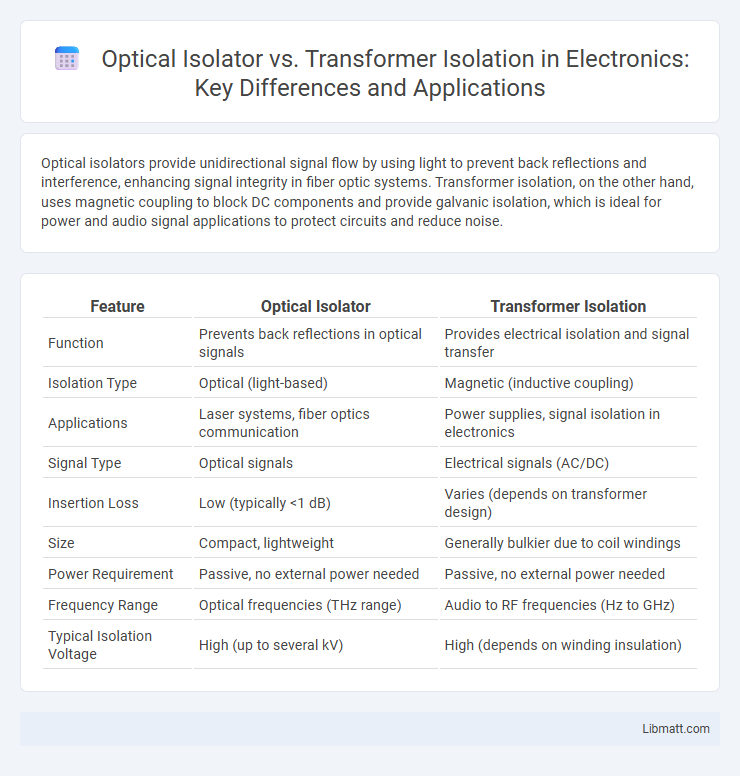
Optical isolators provide unidirectional signal flow by using light to prevent back reflections and interference, enhancing signal integrity in fiber optic systems. Transformer isolation, on the other hand, uses magnetic coupling to block DC components and provide galvanic isolation, which is ideal for power and audio signal applications to protect circuits and reduce noise.
Table of Comparison
| Feature | Optical Isolator | Transformer Isolation |
|---|---|---|
| Function | Prevents back reflections in optical signals | Provides electrical isolation and signal transfer |
| Isolation Type | Optical (light-based) | Magnetic (inductive coupling) |
| Applications | Laser systems, fiber optics communication | Power supplies, signal isolation in electronics |
| Signal Type | Optical signals | Electrical signals (AC/DC) |
| Insertion Loss | Low (typically <1 dB) | Varies (depends on transformer design) |
| Size | Compact, lightweight | Generally bulkier due to coil windings |
| Power Requirement | Passive, no external power needed | Passive, no external power needed |
| Frequency Range | Optical frequencies (THz range) | Audio to RF frequencies (Hz to GHz) |
| Typical Isolation Voltage | High (up to several kV) | High (depends on winding insulation) |
Introduction to Isolation Techniques
Optical isolators use light to achieve electrical isolation by allowing signals to pass in only one direction, preventing feedback and ensuring signal integrity in fiber optic systems. Transformer isolation employs electromagnetic induction through coils to transfer signals while blocking direct electrical current, widely used in power supplies and audio equipment for noise reduction. Both techniques provide critical isolation to protect circuits, enhance signal quality, and maintain system stability in various electronic and communication applications.
What is an Optical Isolator?
An optical isolator is a non-reciprocal device that allows light to pass in only one direction, preventing back reflections that can disrupt laser operation. Unlike transformer isolation, which uses electromagnetic coupling to isolate electrical circuits, optical isolators use magneto-optic effects to protect sensitive components in fiber optic communication and laser systems. Your optical setup can achieve enhanced signal integrity and device protection by incorporating a properly designed optical isolator.
Fundamentals of Transformer Isolation
Transformer isolation operates by using electromagnetic induction between primary and secondary coils to transfer electrical signals while electrically isolating circuits, providing galvanic isolation that prevents direct current flow. It effectively blocks high-frequency noise and surges, enabling safe voltage level shifts and protecting sensitive equipment in power supplies and signal transmission. Its reliance on magnetic coupling enables bidirectional signal transfer with inherent robustness against ground loops and common-mode voltages.
Working Principles: Optical vs Transformer
Optical isolators utilize the Faraday effect to allow unidirectional light transmission, preventing back reflections in fiber optic systems by rotating the polarization of the light. Transformer isolation operates on electromagnetic induction, transferring electrical energy between circuits while providing galvanic separation to block unwanted current flow and noise. Both techniques ensure signal integrity but rely on fundamentally different physical principles: photonic manipulation in isolators versus magnetic coupling in transformers.
Key Differences in Isolation Methods
Optical isolators use light signals and photonic components to achieve electrical isolation by preventing back reflections in fiber optic systems, while transformer isolation relies on magnetic coupling through coils and cores to block direct current flow and noise in electrical circuits. Your choice depends on signals involved; optical isolators suit high-speed data transmission with minimal signal loss, whereas transformer isolation excels in power systems and analog signal conditioning. Both provide galvanic isolation but differ in application scope and physical principles.
Advantages of Optical Isolation
Optical isolation provides superior electrical noise immunity by using light to transmit signals, effectively preventing ground loops and high-voltage surges from damaging sensitive components. Compared to transformer isolation, optical isolators offer faster switching speeds and smaller size, enabling more compact and reliable circuit designs. Your systems benefit from enhanced safety and signal integrity, especially in environments with high electromagnetic interference or where precise signal separation is critical.
Benefits of Transformer Isolation
Transformer isolation provides superior voltage isolation and noise reduction by physically separating input and output circuits, effectively minimizing ground loop interference in sensitive electronic systems. Its ability to handle high power levels and withstand large voltage surges enhances system safety and reliability, making it ideal for power supplies and audio equipment. Unlike optical isolators, transformers do not require a power source, resulting in lower energy consumption and enhanced long-term durability.
Common Applications Compared
Optical isolators are commonly used in fiber optic communication systems to prevent back reflections and signal degradation, ensuring unidirectional light transmission in lasers and amplifiers. Transformer isolation is prevalent in power supplies, audio equipment, and industrial control systems to provide galvanic isolation, protect circuits from voltage spikes, and reduce noise interference. While optical isolators excel in high-frequency and optical signal integrity applications, transformer isolation is preferred for electrical safety and noise reduction in low-frequency and power systems.
Limitations and Challenges
Optical isolators face limitations such as bandwidth restrictions and sensitivity to polarization, which can affect signal integrity in high-speed optical communication. Transformer isolation struggles with size constraints and magnetic interference, limiting its effectiveness in compact and high-frequency applications. Both technologies encounter challenges in integration with modern electronic circuits, impacting overall system efficiency and performance.
Choosing the Right Isolation Technique
Choosing the right isolation technique depends on the application's voltage levels, frequency, and signal type; optical isolators provide excellent high-speed signal isolation with low noise and high common-mode rejection, making them ideal for digital communication and control circuits. Transformer isolation excels in AC power transfer and impedance matching for audio and power systems, offering galvanic isolation and voltage step-up or step-down capabilities. Evaluating factors such as bandwidth, power handling, and environmental conditions ensures optimal performance and system safety in the selected isolation method.
Optical Isolator vs Transformer Isolation Infographic