Pull-up resistors connect a signal line to a positive voltage source, ensuring that the input reads a high logic level when no other active device is driving the line. Pull-down resistors connect the line to ground, guaranteeing a low logic level under similar conditions; understanding the difference helps you design reliable digital circuits by preventing floating states and ensuring stable input signals.
Table of Comparison
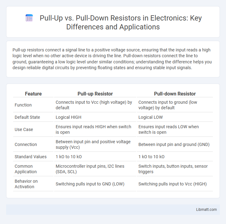
| Feature | Pull-up Resistor | Pull-down Resistor |
|---|---|---|
| Function | Connects input to Vcc (high voltage) by default | Connects input to ground (low voltage) by default |
| Default State | Logical HIGH | Logical LOW |
| Use Case | Ensures input reads HIGH when switch is open | Ensures input reads LOW when switch is open |
| Connection | Between input pin and positive voltage supply (Vcc) | Between input pin and ground (GND) |
| Standard Values | 1 kO to 10 kO | 1 kO to 10 kO |
| Common Application | Microcontroller input pins, I2C lines (SDA, SCL) | Switch inputs, button inputs, sensor triggers |
| Behavior on Activation | Switching pulls input to GND (LOW) | Switching pulls input to Vcc (HIGH) |
Understanding Pull-Up and Pull-Down Resistors
Pull-up and pull-down resistors stabilize input signals in digital circuits by ensuring a defined voltage level when switches or sensors are open or disconnected. A pull-up resistor connects the input pin to a positive voltage (usually Vcc), guaranteeing a default HIGH state, while a pull-down resistor connects the input to ground, securing a default LOW state. Your choice between pull-up and pull-down depends on the desired logic level and circuit design requirements.
How Pull-Up and Pull-Down Resistors Work
Pull-up resistors connect a circuit node to a positive voltage supply, ensuring the input reads a high logic level when no active device drives the line. Pull-down resistors link the node to ground, guaranteeing a low logic level under the same conditions. Both resistors prevent floating inputs, stabilize signal values, and avoid unintended switching in digital electronics.
Key Differences Between Pull-Up and Pull-Down Resistors
Pull-up resistors connect the input pin to a high voltage level (usually Vcc), ensuring the pin reads as logic high when no active signal is present, while pull-down resistors connect the input to ground, ensuring a steady low logic level. The key difference lies in their default logic state: pull-up resistors default to a high input, and pull-down resistors default to low. Your circuit design choice depends on whether you need the input to default to high or low in the absence of an external signal.
When to Use a Pull-Up Resistor
A pull-up resistor is essential when you need to ensure a digital input pin reads a high voltage level by default, preventing it from floating and detecting false signals. You should use a pull-up resistor when interfacing with components like switches or transistors that connect the input to ground when activated, ensuring a stable and predictable logic high state when inactive. Proper use of pull-up resistors enhances signal reliability and prevents unintended noise in your electronic circuits.
When to Use a Pull-Down Resistor
A pull-down resistor is essential when ensuring a digital input pin defaults to a low logic level (0 volts) in the absence of an active signal, preventing floating inputs that cause unpredictable behavior. It is commonly used in circuits with switches, buttons, or sensors that connect the input to a high voltage when activated, ensuring the line reads as low when inactive. Pull-down resistors typically range from 10kO to 100kO, balancing between power consumption and noise immunity.
Common Applications in Digital Circuits
Pull-up and pull-down resistors are essential in digital circuits to ensure defined voltage levels on input pins, preventing floating states that cause erratic behavior. Pull-up resistors connect inputs to a high logic level (usually Vcc) in switches or microcontroller inputs, ensuring a default HIGH state when the switch is open. Pull-down resistors tie inputs to ground (GND), providing a default LOW state, commonly used in buttons and sensors to guarantee predictable input signals for your digital devices.
Calculating Resistor Values for Pull-Up and Pull-Down
Calculating resistor values for pull-up and pull-down circuits depends on balancing power consumption and noise immunity, typically selecting resistors between 1 kO and 100 kO. Lower resistor values (e.g., 1 kO to 10 kO) provide stronger noise suppression but increase current draw, while higher values (e.g., 10 kO to 100 kO) reduce power consumption at the cost of slower response times and susceptibility to interference. Optimal pull-up or pull-down resistor values ensure reliable input signal levels without excessive power dissipation in logic circuits.
Circuit Examples and Schematics
Pull-up resistors connect an input pin to a high voltage level (usually Vcc) to ensure a defined logic high state when no active device is driving the line, as shown in circuits where switches pull the input low to ground. Pull-down resistors, conversely, connect an input to ground to maintain a logic low state until driven high by an external source; typical schematics include push-button inputs that pull the line high when pressed. Both resistors prevent floating inputs, reduce noise, and are commonly depicted in microcontroller input pin configurations with clear resistor placement between the input and either Vcc or ground.
Advantages and Disadvantages of Each Type
Pull-up resistors ensure a default high logic level, preventing floating inputs and reducing noise sensitivity, but they can slightly increase power consumption when the input is driven low. Pull-down resistors provide a default low logic level, which is beneficial in circuits that need to detect high signals, yet they may cause leakage current when the input is high, affecting energy efficiency. Selection depends on the specific logic requirements and power considerations of the circuit design.
Troubleshooting Common Issues
Pull-up and pull-down resistors often cause issues such as floating inputs, leading to unpredictable digital signals or erratic behavior in circuits. Troubleshooting involves verifying resistor values--typically 10kO for general purposes--and ensuring proper connection to the correct voltage level, with pull-up tied to Vcc and pull-down to ground. Using a multimeter to check continuity and signal voltage levels during operation helps identify incorrect wiring or damaged components affecting signal stability.
Pull-up vs Pull-down resistor Infographic