Differential pair signals carry equal and opposite currents, maximizing noise rejection and improving signal integrity by focusing on voltage differences, while common mode signals are the identical voltages present on both lines that can introduce noise and interference. Understanding your system's susceptibility to common mode noise is crucial for designing effective differential signaling and ensuring reliable communication.
Table of Comparison
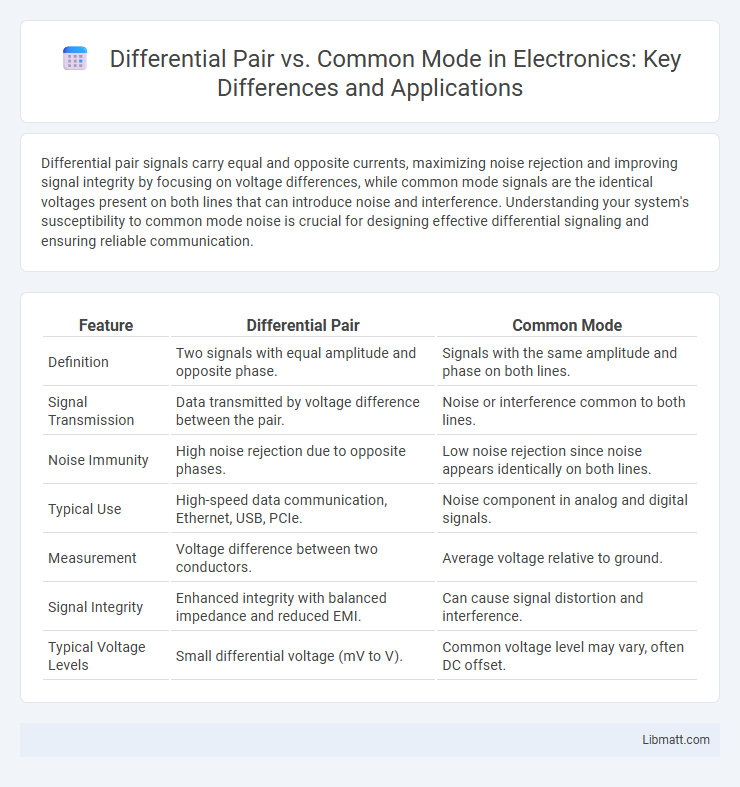
| Feature | Differential Pair | Common Mode |
|---|---|---|
| Definition | Two signals with equal amplitude and opposite phase. | Signals with the same amplitude and phase on both lines. |
| Signal Transmission | Data transmitted by voltage difference between the pair. | Noise or interference common to both lines. |
| Noise Immunity | High noise rejection due to opposite phases. | Low noise rejection since noise appears identically on both lines. |
| Typical Use | High-speed data communication, Ethernet, USB, PCIe. | Noise component in analog and digital signals. |
| Measurement | Voltage difference between two conductors. | Average voltage relative to ground. |
| Signal Integrity | Enhanced integrity with balanced impedance and reduced EMI. | Can cause signal distortion and interference. |
| Typical Voltage Levels | Small differential voltage (mV to V). | Common voltage level may vary, often DC offset. |
Introduction to Differential Pair and Common Mode
Differential pair signals consist of two complementary voltages transmitted over paired conductors, designed to improve noise immunity and signal integrity by canceling common-mode noise. Common mode refers to signals or noise that appear identically on both lines of the pair, typically caused by external interference or ground potential differences. Understanding the distinction between differential and common mode is crucial for optimizing your high-speed PCB designs and minimizing electromagnetic interference.
Fundamental Concepts: Differential and Common Mode Signals
Differential signals consist of two complementary voltages transmitted over a pair of conductors, enhancing noise immunity by allowing receivers to detect the voltage difference between the lines. Common mode signals are identical voltages present on both conductors relative to a common reference, often caused by external interference or ground potential differences. Understanding the fundamental distinction between differential and common mode signals is crucial for designing high-speed communication systems and minimizing electromagnetic interference.
How Differential Pair Works
A differential pair works by transmitting two complementary signals through matched impedance traces, allowing the receiver to measure the voltage difference between them. This technique reduces electromagnetic interference and noise, as any common-mode signals affecting both lines are canceled out. Your data integrity improves significantly in high-speed communication by using differential signaling to enhance signal quality and reduce errors.
Understanding Common Mode Signals
Common mode signals refer to voltage components that appear simultaneously and in-phase on both lines of a differential pair relative to a common ground. These signals often originate from external electromagnetic interference or ground potential differences, affecting the integrity of signal transmission. Effective differential pair design minimizes the impact of common mode noise by ensuring that only the voltage difference between the two conductors carries the intended signal.
Key Differences: Differential Pair vs Common Mode
Differential pair signals consist of two complementary voltages that carry equal and opposite signals, enhancing noise immunity by rejecting common-mode interference. Common mode signals are identical voltages present on both lines relative to a common reference, often resulting in unwanted noise or interference in data transmission. Understanding the distinction between differential pair and common mode is crucial for optimizing signal integrity and minimizing electromagnetic interference in your communication systems.
Advantages of Differential Pair Signaling
Differential pair signaling offers superior noise immunity by transmitting equal and opposite signals, which effectively cancels out common mode noise and electromagnetic interference. This method enhances signal integrity and allows for higher data rates and longer transmission distances compared to single-ended signals. Additionally, differential signaling reduces electromagnetic emissions, improving overall system performance in high-speed communication and sensitive electronic applications.
Common Mode Interference and Its Impact
Common mode interference occurs when unwanted signals appear simultaneously and in-phase on both lines of a differential pair, leading to noise that can degrade signal integrity. Differential pair design inherently rejects common mode noise by relying on the voltage difference between the two conductors, which enhances noise immunity in high-speed data transmission. However, excessive common mode interference can induce electromagnetic emissions and increase bit error rates, necessitating careful PCB layout and shielding strategies to minimize its impact.
Applications of Differential Pair Transmission
Differential pair transmission is widely used in high-speed data communication applications such as USB, HDMI, and Ethernet to reduce electromagnetic interference and improve signal integrity. It enables better noise immunity by transmitting two complementary signals over paired conductors, allowing receivers to detect differences rather than absolute voltages. Common-mode noise is effectively rejected, making differential pairs ideal for environments with significant electrical noise or long cable runs.
Techniques for Minimizing Common Mode Noise
Minimizing common mode noise in differential pair systems involves precise PCB layout techniques such as maintaining tight coupling and equal trace lengths to ensure signal integrity. Implementing common mode chokes and proper grounding reduces noise coupling by filtering unwanted currents without affecting differential signals. Using differential signaling inherently cancels out common mode interference by transmitting inverted signals on matched pairs, greatly enhancing noise immunity.
Choosing Between Differential Pair and Common Mode Designs
Choosing between differential pair and common mode designs depends on your application's noise rejection and signal integrity requirements. Differential pairs, with two complementary signals, excel at minimizing electromagnetic interference and crosstalk, making them ideal for high-speed data transmission and sensitive analog circuits. Common mode designs, which reference signals to a shared ground, offer simplicity and cost-effectiveness but may be more susceptible to noise in electrically noisy environments.
Differential Pair vs Common Mode Infographic