AC coupling blocks the DC component of a signal, allowing only alternating current (AC) signals to pass through, which is useful for removing unwanted DC offsets in measurement systems. DC coupling, on the other hand, allows both AC and DC components to pass, preserving the original waveform and enabling accurate voltage level detection in your electronic circuits.
Table of Comparison
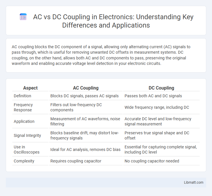
| Aspect | AC Coupling | DC Coupling |
|---|---|---|
| Definition | Blocks DC signals, passes AC signals | Passes both AC and DC signals |
| Frequency Response | Filters out low-frequency DC components | Wide frequency range, including DC |
| Application | Measurement of AC waveforms, noise filtering | Accurate DC level and low-frequency signal measurement |
| Signal Integrity | Blocks baseline drift, may distort low-frequency signals | Preserves true signal shape and DC offset |
| Use in Oscilloscopes | Ideal for AC analysis, removes DC bias | Essential for capturing complete signal, including DC level |
| Complexity | Requires coupling capacitor | No coupling capacitor needed |
Introduction to AC and DC Coupling
AC coupling filters out the DC component of a signal, allowing only the alternating current (AC) part to pass through, which is essential for measuring varying signals without offset interference. DC coupling enables both the AC and DC components to pass, preserving the signal's true voltage levels and is crucial for accurate representation of steady-state signals. Understanding the differences between AC and DC coupling helps optimize signal analysis in oscilloscopes, amplifiers, and communication systems.
Fundamentals of Signal Coupling
Signal coupling involves transferring electrical signals between circuits while managing unwanted components. AC coupling uses a capacitor to block DC components, allowing only varying signals to pass, which is essential for isolating DC offsets in amplifiers or oscilloscopes. DC coupling transfers both AC and DC signals directly, preserving the complete waveform, making it suitable for low-frequency or steady-state signal analysis where true voltage levels are critical.
How AC Coupling Works
AC coupling works by using a capacitor to block direct current (DC) components in a signal, allowing only alternating current (AC) variations to pass through. This method removes any DC offset, enabling accurate measurement of the AC signal's variations without the influence of a steady voltage level. In oscilloscopes and signal processing, AC coupling is essential for analyzing small AC signals superimposed on large DC offsets.
How DC Coupling Works
DC coupling allows direct transmission of both alternating and direct current signals by maintaining a continuous electrical connection between the source and the measurement device. This method preserves the true DC component of the signal, enabling accurate measurement of low-frequency or steady-state voltages. Your devices benefit from DC coupling when detecting slow signal variations or static voltage levels that AC coupling would filter out.
Key Differences Between AC and DC Coupling
AC coupling blocks DC signals and allows only alternating current signals to pass, making it ideal for measuring small AC signals on top of a large DC offset. DC coupling transmits both AC and DC components, preserving the full signal waveform, which is essential for analyzing low-frequency or static signals accurately. Your choice between AC and DC coupling depends on whether the DC component is relevant to the measurement or if isolating the AC variations is more critical.
Advantages of AC Coupling
AC coupling effectively blocks DC offset voltage, preventing signal distortion and protecting sensitive measurement equipment. It is ideal for isolating AC signals in environments with varying ground potentials, thus avoiding ground loop interference. This method enhances signal integrity in high-frequency applications, ensuring clearer and more accurate waveform analysis.
Benefits of DC Coupling
DC coupling enables direct transmission of both AC and DC signals without distortion, preserving signal integrity for sensitive applications such as sensor data acquisition and communication systems. It allows accurate measurement of low-frequency and static signals by maintaining the true baseline voltage, which is essential in medical devices and precision instrumentation. The absence of capacitors in the signal path reduces signal loss and phase shift, enhancing overall system performance and reliability.
Applications of AC and DC Coupling
AC coupling is commonly used in signal processing applications where blocking DC offsets is crucial, such as in audio equipment and oscilloscopes measuring AC signals. DC coupling is preferred for applications requiring accurate measurement of both AC and DC components, including sensor data acquisition and power supply monitoring. Understanding the distinction helps you select the appropriate method for precise signal analysis in various electronic and communication systems.
Choosing Between AC and DC Coupling
Choosing between AC and DC coupling depends on the signal type and measurement objectives. AC coupling blocks DC components to focus on alternating signals, ideal for analyzing small AC variations superimposed on large DC offsets. Your choice influences measurement accuracy and waveform representation in oscilloscopes, making it essential to match coupling type with the signal characteristics.
Conclusion: Selecting the Right Coupling Method
Selecting the right coupling method depends on your specific signal requirements and application context. AC coupling blocks DC components, making it ideal for isolating signal variations without bias, while DC coupling preserves the entire signal waveform, including DC levels. Understanding the nature of your signal and measurement goals ensures optimal system performance and accuracy.
AC vs DC coupling Infographic