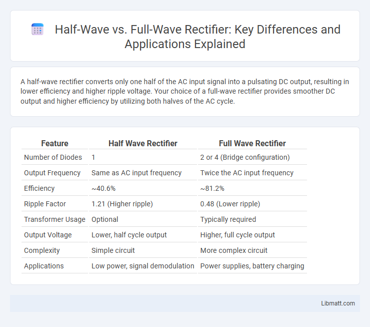
A half-wave rectifier converts only one half of the AC input signal into a pulsating DC output, resulting in lower efficiency and higher ripple voltage. Your choice of a full-wave rectifier provides smoother DC output and higher efficiency by utilizing both halves of the AC cycle.
Table of Comparison
| Feature | Half Wave Rectifier | Full Wave Rectifier |
|---|---|---|
| Number of Diodes | 1 | 2 or 4 (Bridge configuration) |
| Output Frequency | Same as AC input frequency | Twice the AC input frequency |
| Efficiency | ~40.6% | ~81.2% |
| Ripple Factor | 1.21 (Higher ripple) | 0.48 (Lower ripple) |
| Transformer Usage | Optional | Typically required |
| Output Voltage | Lower, half cycle output | Higher, full cycle output |
| Complexity | Simple circuit | More complex circuit |
| Applications | Low power, signal demodulation | Power supplies, battery charging |
Introduction to Rectifiers
Rectifiers convert alternating current (AC) to direct current (DC) by allowing current to flow in only one direction, essential for powering DC electronics. Half wave rectifiers use a single diode to conduct during one half-cycle of AC, resulting in lower efficiency and higher ripple voltage. Full wave rectifiers employ multiple diodes or a center-tapped transformer to utilize both half-cycles of AC, providing smoother DC output with reduced ripple and improved efficiency.
What is a Half Wave Rectifier?
A Half Wave Rectifier is an electrical device that converts alternating current (AC) into direct current (DC) by allowing only one half-cycle of the AC waveform to pass through, effectively blocking the other half. This rectifier uses a single diode, resulting in lower efficiency and more ripple compared to a Full Wave Rectifier, which utilizes both half-cycles. Understanding the operation of a Half Wave Rectifier helps you choose the appropriate rectification method for simple or low-power electronic applications.
What is a Full Wave Rectifier?
A Full Wave Rectifier is an electronic circuit that converts the entire input alternating current (AC) waveform into a pulsating direct current (DC). It utilizes both halves of the AC cycle, doubling the output frequency compared to a Half Wave Rectifier and providing improved efficiency and smoother output voltage. Your electronic applications benefit from reduced ripple voltage and enhanced power delivery when using a Full Wave Rectifier.
Circuit Diagrams and Working Principles
A half wave rectifier uses a single diode to convert AC to pulsating DC by allowing current flow during only one half-cycle of the input signal, resulting in a simpler circuit diagram but lower efficiency. In contrast, a full wave rectifier employs either two diodes with a center-tapped transformer or four diodes in a bridge configuration, enabling current flow during both positive and negative half-cycles, which doubles the frequency of the output pulsating DC and improves efficiency. Understanding these circuit diagrams and working principles helps you choose the right rectifier type for applications requiring specific voltage regulation and current handling capabilities.
Key Differences Between Half Wave and Full Wave Rectifiers
Half wave rectifiers allow current to pass through only one half of the AC cycle, resulting in lower efficiency and higher ripple voltage, whereas full wave rectifiers convert both halves of the AC cycle into DC, providing smoother output and higher efficiency. The peak inverse voltage rating in full wave rectifiers is typically lower compared to half wave rectifiers, making them more suitable for high power applications. Understanding these key differences enables you to choose the right rectifier for your power conversion needs.
Efficiency Comparison
A full wave rectifier typically offers higher efficiency than a half wave rectifier by converting both halves of the AC input into DC output, resulting in approximately 80-90% efficiency compared to the half wave's 40-50%. The continuous conduction in a full wave rectifier reduces ripple voltage and improves power delivery to your load, making it more suitable for applications requiring steady DC voltage. Understanding these efficiency differences helps optimize your circuit design for maximum performance and energy savings.
Ripple Factor Analysis
Half wave rectifiers exhibit a higher ripple factor, typically around 1.21, which results in more significant voltage fluctuations and less smoothing in the output signal. Full wave rectifiers have a lower ripple factor, approximately 0.482, producing a more stable and smoother DC output due to rectification of both positive and negative halves of the input AC waveform. The reduced ripple factor in full wave rectifiers improves efficiency and reduces the need for extensive filtering in power supply circuits.
Applications of Half Wave Rectifiers
Half wave rectifiers are commonly used in low-power applications such as signal demodulation, small power supplies, and battery charging circuits. Their simple design makes them suitable for devices that do not require high efficiency or smooth DC output, including radios and basic power adapters. Despite their limitations in efficiency and ripple, half wave rectifiers provide cost-effective solutions in these specific electronic applications.
Applications of Full Wave Rectifiers
Full wave rectifiers are extensively used in power supply units for converting AC to DC in devices such as battery chargers, DC motor drives, and radio signal demodulators. Their ability to provide higher average output voltage and improved efficiency makes them ideal for industrial power systems and household electronic equipment. The waveform smoothing capabilities of full wave rectifiers enhance performance in audio amplifiers and regulated power supplies.
Summary and Conclusion
A half wave rectifier uses a single diode to convert AC to DC, allowing current flow only during one half-cycle and producing a pulsating output with lower efficiency. A full wave rectifier employs two or more diodes to rectify both half-cycles of the AC input, resulting in a higher average output voltage, improved efficiency, and smoother DC output. Full wave rectifiers are preferred in power supply applications due to their superior performance, reduced ripple, and better transformer utilization compared to half wave rectifiers.
Half Wave vs Full Wave Rectifier Infographic