Sine output delivers a smooth, continuous waveform ideal for sensitive electronics and audio applications, providing cleaner power with reduced harmonic distortion. PWM output switches rapidly between on and off states to simulate analog signals, offering efficient power control and improved energy savings for motor drives and LED dimming.
Table of Comparison
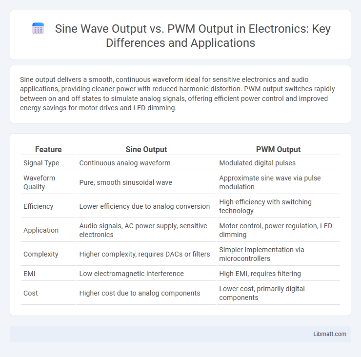
| Feature | Sine Output | PWM Output |
|---|---|---|
| Signal Type | Continuous analog waveform | Modulated digital pulses |
| Waveform Quality | Pure, smooth sinusoidal wave | Approximate sine wave via pulse modulation |
| Efficiency | Lower efficiency due to analog conversion | High efficiency with switching technology |
| Application | Audio signals, AC power supply, sensitive electronics | Motor control, power regulation, LED dimming |
| Complexity | Higher complexity, requires DACs or filters | Simpler implementation via microcontrollers |
| EMI | Low electromagnetic interference | High EMI, requires filtering |
| Cost | Higher cost due to analog components | Lower cost, primarily digital components |
Understanding Sine Wave Output
Sine output provides a smooth and continuous waveform that closely mimics the natural AC electricity typically found in household power, ensuring better compatibility with sensitive electronic devices. PWM output, by contrast, uses pulse width modulation to approximate a sine wave, resulting in a less pure signal that can introduce noise and inefficiencies in certain applications. Understanding the quality difference between sine wave output and PWM output helps you choose the right power source for your equipment's optimal performance and longevity.
What is PWM Output?
PWM output, or Pulse Width Modulation output, controls power delivery by varying the width of pulses in a fixed frequency signal, allowing efficient management of electrical devices such as motors and LEDs. Unlike sine output, which provides smooth, continuous waves, PWM output delivers rapid on/off switching, optimizing energy use and reducing heat generation. Your choice between sine and PWM output depends on the application's need for precision, efficiency, and control.
Key Differences Between Sine and PWM Outputs
Sine output delivers a smooth, continuous waveform closely matching the ideal AC power signal, minimizing harmonic distortion and ensuring compatibility with sensitive electronics. PWM (Pulse Width Modulation) output produces a switched, square-like waveform by rapidly toggling voltage on and off, which is easier and cheaper to generate but introduces higher total harmonic distortion and potential electromagnetic interference. Devices requiring clean power signals, such as audio equipment or variable speed motors, benefit from sine wave output, while PWM output suits simpler loads and cost-sensitive applications.
Efficiency Comparison: Sine vs PWM
Sine output in inverters provides smooth, clean power ideal for sensitive electronics, but typically results in lower efficiency due to complex filtering and waveform generation. PWM output improves efficiency by switching between on and off states rapidly, minimizing power loss and enhancing battery life in DC systems. Your choice depends on whether efficiency or waveform quality is more critical for your application.
Signal Quality and Harmonics
Sine output provides a smooth waveform with low total harmonic distortion (THD), resulting in high signal quality ideal for sensitive electronic devices. PWM output generates a pulsed waveform composed of multiple harmonics, leading to higher THD and potential electromagnetic interference (EMI). The clean sine wave minimizes harmonic noise, whereas PWM output requires filtering to reduce harmonic distortion and improve power quality.
Applications of Sine Output
Sine output is widely used in applications requiring smooth and continuous waveforms, such as audio amplifiers, AC motor drives, and signal processing in communication systems. It offers reduced harmonic distortion, ensuring high power quality for sensitive electronic equipment and renewable energy systems like solar inverters. Precision in generating sine output enhances performance in medical devices and instrumentation where waveform purity is critical.
Applications of PWM Output
PWM output is widely used in motor speed control, LED dimming, and power regulation due to its efficient modulation of voltage and current. It enables precise control of power delivery in embedded systems, robotics, and automotive electronics. PWM signals are essential in switching power supplies and communication systems for optimizing energy efficiency and signal integrity.
Impact on Electronic Devices
Sine output provides a smooth, continuous waveform that closely mimics natural AC power, reducing harmonic distortion and minimizing stress on electronic devices such as motors, transformers, and sensitive equipment. PWM output generates a pulsed waveform that can cause higher electrical noise, heat, and potential interference, potentially shortening the lifespan of your electronic devices. Choosing sine output over PWM can improve the efficiency and longevity of your electronics by delivering cleaner energy with lower electromagnetic interference.
Cost Considerations: Sine vs PWM
Sine wave output typically involves more complex and expensive components such as specialized inverter circuits and filters, resulting in higher initial costs compared to PWM output systems. PWM output uses simpler switching techniques with standard components, making it a cost-effective solution for many applications. However, the added expense of sine wave systems can be justified by improved efficiency and reduced harmonic distortion in sensitive electronic devices.
Choosing the Right Output for Your Needs
Sine output provides smooth, continuous waveforms ideal for sensitive electronics and audio applications, ensuring minimal harmonic distortion and efficient motor performance. PWM output offers precise control through rapid switching, enhancing energy efficiency and flexibility in power regulation for LED dimming and motor speed control. Selecting the right output depends on specific application requirements, balancing waveform purity against control granularity and system complexity.
Sine output vs PWM output Infographic