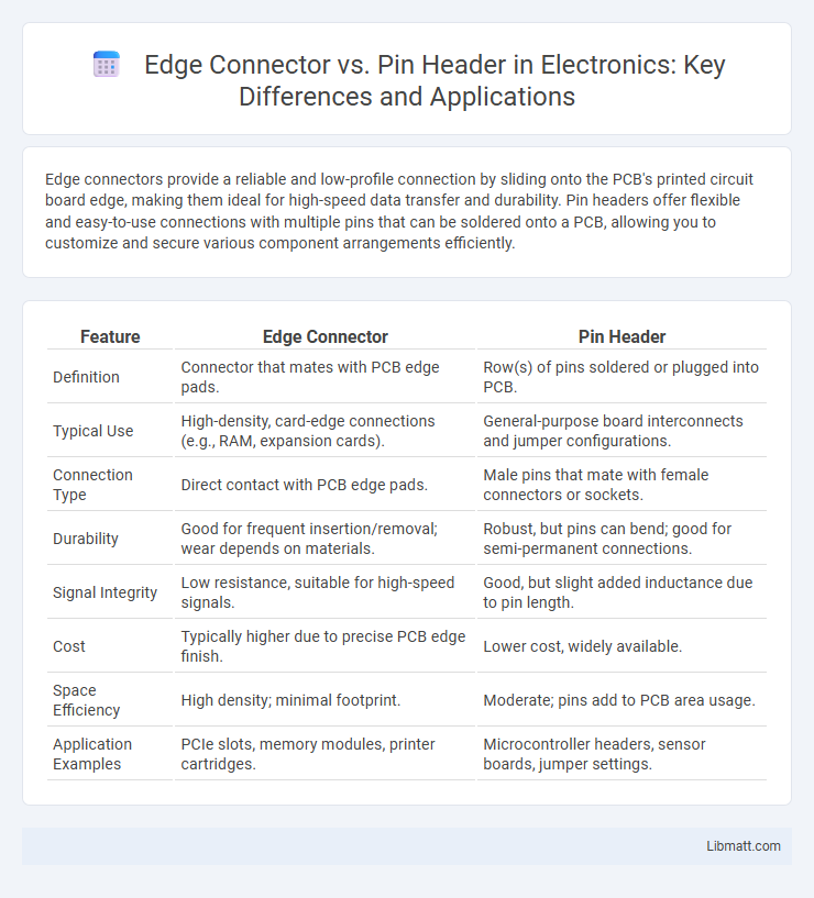
Edge connectors provide a reliable and low-profile connection by sliding onto the PCB's printed circuit board edge, making them ideal for high-speed data transfer and durability. Pin headers offer flexible and easy-to-use connections with multiple pins that can be soldered onto a PCB, allowing you to customize and secure various component arrangements efficiently.
Table of Comparison
| Feature | Edge Connector | Pin Header |
|---|---|---|
| Definition | Connector that mates with PCB edge pads. | Row(s) of pins soldered or plugged into PCB. |
| Typical Use | High-density, card-edge connections (e.g., RAM, expansion cards). | General-purpose board interconnects and jumper configurations. |
| Connection Type | Direct contact with PCB edge pads. | Male pins that mate with female connectors or sockets. |
| Durability | Good for frequent insertion/removal; wear depends on materials. | Robust, but pins can bend; good for semi-permanent connections. |
| Signal Integrity | Low resistance, suitable for high-speed signals. | Good, but slight added inductance due to pin length. |
| Cost | Typically higher due to precise PCB edge finish. | Lower cost, widely available. |
| Space Efficiency | High density; minimal footprint. | Moderate; pins add to PCB area usage. |
| Application Examples | PCIe slots, memory modules, printer cartridges. | Microcontroller headers, sensor boards, jumper settings. |
Introduction to Edge Connectors and Pin Headers
Edge connectors provide a reliable and compact method for connecting printed circuit boards (PCBs) by utilizing exposed copper traces on the board's edge that mate with a corresponding socket. Pin headers consist of rows of metal pins soldered directly onto the PCB, offering a versatile and modular connection interface compatible with various wire connectors and jumper cables. Both edge connectors and pin headers play crucial roles in electronics assembly, influencing signal integrity, mechanical strength, and ease of maintenance.
Key Differences Between Edge Connectors and Pin Headers
Edge connectors feature a flat, card-edge interface designed for PCBs, offering reliable high-speed signal transmission and easy insertion/removal, while pin headers consist of rows of metal pins for versatile connections in various electronics. Edge connectors excel in applications requiring robust mechanical stability and frequent mating cycles, whereas pin headers provide flexibility for prototyping and modular connections with standard spacing. The choice depends on factors like signal integrity needs, mechanical durability, and design compatibility with existing hardware.
Common Applications of Edge Connectors
Edge connectors are commonly used in applications requiring robust, high-density connections such as printed circuit boards (PCBs) for computer memory modules, expansion cards, and industrial equipment interfaces. They provide reliable, quick mating and unmating capabilities essential for devices like graphics cards, game consoles, and telecommunications hardware. Their design facilitates high-speed signal transmission, making them ideal for PCI, PCIe, and other high-performance interconnect standards.
Typical Uses of Pin Headers
Pin headers are commonly used in printed circuit boards (PCBs) to provide a reliable and removable electrical connection between components and peripherals. They are ideal for prototyping, connecting sensors, modules, and microcontrollers, enabling easy customization and testing during development stages. Pin headers support a variety of connector types, including female headers, jumper wires, and ribbon cables, making them versatile for both industrial and hobbyist applications.
Electrical Performance Comparison
Edge connectors offer superior electrical performance with lower contact resistance and improved signal integrity due to their larger contact surfaces compared to pin headers. Pin headers may introduce higher inductance and capacitance, potentially causing signal degradation in high-frequency applications. Your choice should consider the operating frequency and current requirements, as edge connectors excel in minimizing signal loss and noise in demanding electrical environments.
Mechanical Durability and Reliability
Edge connectors provide superior mechanical durability and reliability compared to pin headers due to their robust design that ensures consistent contact pressure and reduces wear over repeated insertions. Pin headers, while versatile, are more prone to bending or damage because the individual pins can deform or misalign under mechanical stress. For your applications requiring frequent mating cycles and strong connection integrity, edge connectors offer a more reliable solution with enhanced resistance to mechanical fatigue.
Space and Form Factor Considerations
Edge connectors provide a compact and low-profile solution, ideal for applications with limited space due to their direct PCB contact without additional components. Pin headers, while more versatile for various cable connections, require extra clearance above the PCB, impacting the overall form factor and potentially increasing the device's height. Selecting between edge connectors and pin headers depends on balancing space constraints with mechanical durability and assembly requirements.
Ease of Assembly and Maintenance
Edge connectors offer quicker and more straightforward assembly due to their tool-free insertion design, reducing the risk of bent or damaged pins during installation. Pin headers require careful alignment and soldering, which can increase assembly time and complicate maintenance tasks like replacement or rework. The ease of unplugging and reinserting edge connectors also enhances maintenance efficiency compared to the more rigid and less forgiving nature of pin headers.
Cost Analysis: Edge Connector vs Pin Header
Edge connectors typically offer a cost advantage in high-volume production due to simpler manufacturing and fewer components required compared to pin headers, which involve multiple individual pins and plastic housing. Pin headers, however, may incur higher assembly costs and potential alignment issues, increasing overall expenses in complex or high-pin-count applications. For budget-sensitive projects with moderate pin counts, edge connectors provide a more economical and reliable solution.
Choosing the Right Connector for Your Project
Edge connectors provide a compact, reliable connection ideal for high-density circuit boards, offering enhanced signal integrity for faster data transmission. Pin headers deliver versatility and ease of use, supporting various wire-to-board connections suitable for prototypes and modular designs. Selecting between edge connectors and pin headers depends on factors such as PCB layout, mechanical strength requirements, and electrical performance demands in your project.
Edge connector vs Pin header Infographic