4-20mA current signals provide greater noise immunity and enable longer cable runs compared to 0-10V voltage signals, making them ideal for industrial environments. Your choice depends on the application, with 4-20mA preferred for precise and reliable control, while 0-10V is simpler and often used in low-noise settings.
Table of Comparison
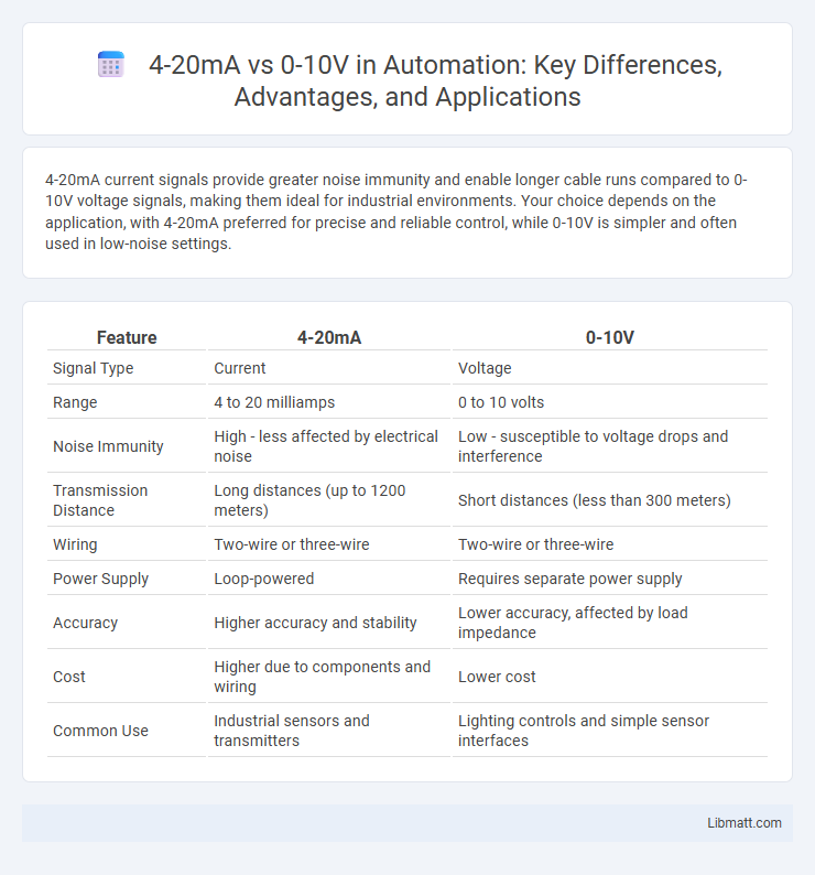
| Feature | 4-20mA | 0-10V |
|---|---|---|
| Signal Type | Current | Voltage |
| Range | 4 to 20 milliamps | 0 to 10 volts |
| Noise Immunity | High - less affected by electrical noise | Low - susceptible to voltage drops and interference |
| Transmission Distance | Long distances (up to 1200 meters) | Short distances (less than 300 meters) |
| Wiring | Two-wire or three-wire | Two-wire or three-wire |
| Power Supply | Loop-powered | Requires separate power supply |
| Accuracy | Higher accuracy and stability | Lower accuracy, affected by load impedance |
| Cost | Higher due to components and wiring | Lower cost |
| Common Use | Industrial sensors and transmitters | Lighting controls and simple sensor interfaces |
Introduction to 4-20mA and 0-10V Signal Standards
4-20mA and 0-10V are widely used industrial signal standards for transmitting analog sensor data in control systems. The 4-20mA current loop offers superior noise immunity and longer transmission distances compared to the voltage-based 0-10V signal, which is more susceptible to voltage drops and interference. Understanding these differences is essential for optimizing sensor accuracy and reliability in automation and process control applications.
Basic Principles of 4-20mA Current Loops
The 4-20mA current loop operates by transmitting signals as a varying current, where 4mA represents the lowest measurement and 20mA the highest, ensuring consistent signal integrity over long distances. Unlike voltage signals, the current remains constant despite resistance changes in the loop, making 4-20mA ideal for industrial environments with electrical noise. Your choice of a 4-20mA system guarantees accurate and reliable sensor communication, critical for precise process control.
Core Concepts of 0-10V Voltage Signals
0-10V voltage signals operate by varying the output voltage between 0 and 10 volts to represent the range of a measured parameter, commonly used in lighting and HVAC control systems. The core concept involves a direct correlation between the applied voltage and the control signal, where 0 volts typically indicates the lowest setting or off state, and 10 volts represents the maximum value or full operation. Unlike current loops such as 4-20mA, 0-10V signals are more susceptible to voltage drop and electrical noise over long distances, requiring careful wiring and shielding for optimal performance.
Accuracy and Signal Integrity Comparison
The 4-20mA current loop provides higher accuracy and better signal integrity over long distances due to its inherent resistance to electrical noise and voltage drop. In contrast, the 0-10V voltage signal is more susceptible to signal degradation and interference, especially in environments with high electromagnetic noise or long cable runs. Consequently, 4-20mA is preferred in industrial control systems where precision and reliable communication are critical.
Wiring and Installation Differences
4-20mA wiring uses a two-wire loop powered system that transmits signals through current variations, offering inherent resistance to electrical noise and allowing longer cable runs without signal degradation. 0-10V uses a three-wire system where the signal voltage varies between 0 and 10 volts, requiring separate power and signal return wires, which makes it more susceptible to voltage drop and interference over long distances. Installation of 4-20mA sensors is generally simpler and more reliable for industrial environments, while 0-10V is often chosen for shorter distances due to easier integration with analog control systems.
Noise Immunity and Transmission Distance
The 4-20mA current loop offers superior noise immunity compared to 0-10V voltage signals because current remains constant despite voltage drops or electromagnetic interference, making it ideal for industrial environments with high electrical noise. Transmission distance is also greater for 4-20mA signals, often exceeding several hundred meters without signal degradation, whereas 0-10V signals typically suffer voltage drop and noise over longer distances, limiting effective range to around 50 meters. For your applications requiring reliable long-distance communication in noisy settings, a 4-20mA interface provides more robust performance than 0-10V.
Application Scenarios for 4-20mA vs 0-10V
4-20mA signals excel in industrial automation and process control environments where long cable runs and electrical noise immunity are critical, ensuring accurate data transmission over extended distances. 0-10V signals are commonly used in building automation and lighting control systems where short cable lengths and simpler wiring setups are sufficient. Your choice depends on the installation complexity, required signal integrity, and environmental factors impacting sensor or actuator performance.
Cost Considerations and System Complexity
4-20mA current loops generally incur higher installation costs due to the need for specialized wiring and current sources but offer superior noise immunity and longer transmission distances, reducing maintenance expenses in industrial environments. 0-10V systems are typically less expensive upfront, utilizing simpler wiring and standard voltage signals, but are more susceptible to signal degradation and interference, which can increase troubleshooting and recalibration costs. System complexity rises with 4-20mA as it requires careful handling of loop powering and compliance voltages, whereas 0-10V control systems are simpler to integrate but may demand additional shielding and signal conditioning for reliable operation.
Maintenance and Troubleshooting Factors
4-20mA signal systems are less susceptible to electrical noise interference, improving maintenance reliability and simplifying troubleshooting by providing a standardized signal range that detects wire breaks as low signals. In contrast, 0-10V systems are more prone to voltage drop issues over long cable runs, requiring frequent voltage level checks during troubleshooting to ensure signal integrity. Maintenance of 4-20mA loops typically involves current measurement tools, while 0-10V systems often need voltage measurements and attention to proper grounding to prevent signal distortion.
Choosing the Right Signal Standard for Your Application
Choosing the right signal standard between 4-20mA and 0-10V depends on the application's distance, interference, and precision requirements. 4-20mA signals excel in long-distance transmission and noisy industrial environments due to their current loop design that resists signal degradation. Your decision should consider that 0-10V signals work well for short-range, low-interference settings with simpler wiring but are more susceptible to voltage drops and noise.
4-20mA vs 0-10V Infographic