Common mode noise affects both lines of a circuit simultaneously with the same voltage, while differential mode noise occurs between two lines with opposite polarity signals. Understanding the distinction helps you implement effective filtering techniques to improve signal integrity and reduce electromagnetic interference.
Table of Comparison
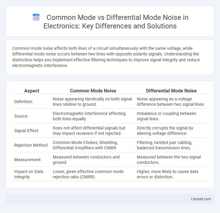
| Aspect | Common Mode Noise | Differential Mode Noise |
|---|---|---|
| Definition | Noise appearing identically on both signal lines relative to ground. | Noise appearing as a voltage difference between two signal lines. |
| Source | Electromagnetic interference affecting both lines equally. | Imbalance or coupling between signal lines. |
| Signal Effect | Does not affect differential signals but may impact receivers if not rejected. | Directly corrupts the signal by altering voltage difference. |
| Rejection Method | Common Mode Chokes, Shielding, Differential Amplifiers with CMRR. | Filtering, twisted pair cabling, balanced transmission lines. |
| Measurement | Measured between conductors and ground. | Measured between the two signal conductors. |
| Impact on Data Integrity | Lower, given effective common mode rejection ratio (CMRR). | Higher, more likely to cause data errors or distortion. |
Introduction to Common Mode and Differential Mode Noise
Common mode noise occurs when unwanted signals appear simultaneously and in phase on both lines of a transmission pair relative to a common ground, while differential mode noise appears as noise signals traveling in opposite phase between the two lines. Understanding the distinction is critical for effective noise reduction and electromagnetic compatibility in electronic circuits and communication systems. Your ability to identify and mitigate these noise types directly impacts signal integrity and system performance.
Understanding Noise in Electronic Circuits
Common mode noise occurs when interference affects both lines of a circuit equally, while differential mode noise affects the lines differentially, impacting signal integrity differently. Understanding noise in electronic circuits requires analyzing how these noise types propagate and interact with components, influencing design choices for filters and shielding. Your ability to identify and mitigate common and differential mode noise ensures enhanced performance and reliability in electronic systems.
What is Common Mode Noise?
Common mode noise refers to unwanted electrical interference that appears identically on both lines of a two-wire system relative to a common ground or reference point. This type of noise often originates from external electromagnetic interference or ground loops, affecting signal integrity and causing disruptions in electronic circuits. Understanding common mode noise is crucial for designing effective filtering and shielding solutions to improve system performance and reduce electromagnetic compatibility (EMC) issues.
What is Differential Mode Noise?
Differential mode noise refers to interference that appears as a voltage difference between two signal lines, typically in a balanced circuit, causing unwanted disturbances in the transmitted data. This type of noise affects the integrity of the signal by creating errors in communication systems, especially in environments with high electromagnetic interference. Understanding differential mode noise is crucial for designing effective filtering and shielding solutions to maintain the accuracy of Your electronic signals.
Key Differences: Common Mode vs Differential Mode Noise
Common mode noise appears equally on both conductors relative to a common ground, while differential mode noise occurs between two conductors carrying opposite signals. Common mode noise typically affects the overall system by coupling external interference, whereas differential mode noise originates from imbalances within the signal path itself. Understanding these key differences helps you implement appropriate filtering techniques to improve signal integrity and reduce electromagnetic interference in electronic circuits.
Sources of Common Mode Noise
Common mode noise originates primarily from external electromagnetic interference (EMI) sources, such as power lines, radio frequency interference (RFI), and ground potential differences between interconnected devices. Ground loops and cable shielding inefficiencies also contribute significantly to common mode noise by allowing unwanted signals to couple into both lines of a differential pair simultaneously. Understanding these sources is crucial for designing effective filtering and grounding strategies to minimize noise impact in sensitive electronic systems.
Sources of Differential Mode Noise
Differential mode noise originates primarily from imbalances in electrical circuits, often caused by switching devices, signal crosstalk, and fast transient changes in current within power lines or data communication paths. This type of noise appears as voltage differences between two conductors, typically induced by load switching, inverter operations, or rapid changes in load conditions. Effective mitigation strategies include the use of differential-mode filters, proper cable shielding, and balanced circuit design to minimize signal distortion and maintain electromagnetic compatibility.
Effects of Noise on Circuit Performance
Common mode noise affects both lines of a circuit simultaneously and can cause signal distortion, reduced signal-to-noise ratio, and potential malfunction in sensitive electronic equipment. Differential mode noise, present between two conductors, can lead to data errors, timing issues, and increased electromagnetic interference, undermining overall circuit reliability. Understanding these noise types helps you design effective filtering and shielding strategies to maintain optimal circuit performance.
Methods for Reducing Common Mode and Differential Mode Noise
Effective methods for reducing common mode noise include the use of common mode chokes and balanced cabling, which help suppress interference by providing high impedance to noise currents while allowing the desired signal to pass. Differential mode noise can be minimized through proper shielding, twisted-pair wiring, and the implementation of differential filters that attenuate unwanted signals between conductors. Careful PCB layout, including grounding strategies and component placement, also plays a critical role in mitigating both common mode and differential mode noise in electronic systems.
Practical Applications and Industry Solutions
Common mode noise typically affects all conductors equally and is prevalent in electromagnetic interference (EMI) filtering for power supplies and data lines, while differential mode noise arises from voltage differences between conductors, impacting signal integrity in communication systems. Industry solutions include common mode chokes and EMI filters to mitigate common mode noise in industrial automation and automotive electronics, whereas differential mode noise is addressed through twisted-pair cables, differential signaling, and balanced transmission lines widely used in telecom and high-speed data networks. Practical applications span from ensuring compliance with EMC standards in consumer electronics to enhancing data transmission reliability in aerospace and medical devices.
Common mode vs Differential mode noise Infographic