Conducted emission refers to unwanted electromagnetic noise transmitted along electrical cables, while radiated emission involves electromagnetic energy that propagates through the air from a device. Understanding the distinction helps you effectively design and implement mitigation strategies to comply with electromagnetic compatibility (EMC) standards.
Table of Comparison
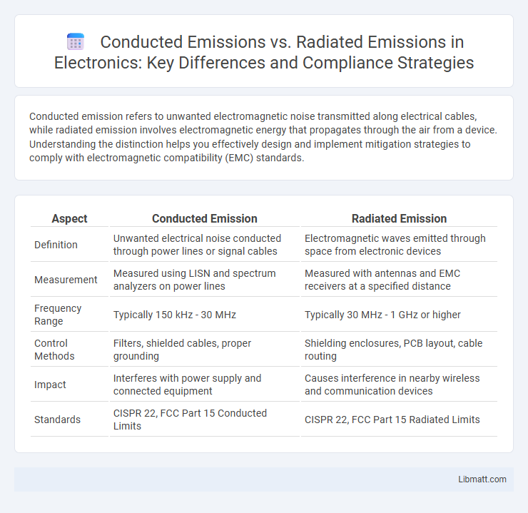
| Aspect | Conducted Emission | Radiated Emission |
|---|---|---|
| Definition | Unwanted electrical noise conducted through power lines or signal cables | Electromagnetic waves emitted through space from electronic devices |
| Measurement | Measured using LISN and spectrum analyzers on power lines | Measured with antennas and EMC receivers at a specified distance |
| Frequency Range | Typically 150 kHz - 30 MHz | Typically 30 MHz - 1 GHz or higher |
| Control Methods | Filters, shielded cables, proper grounding | Shielding enclosures, PCB layout, cable routing |
| Impact | Interferes with power supply and connected equipment | Causes interference in nearby wireless and communication devices |
| Standards | CISPR 22, FCC Part 15 Conducted Limits | CISPR 22, FCC Part 15 Radiated Limits |
Understanding Conducted Emission
Conducted emission refers to the unwanted electromagnetic energy that travels along power or signal cables, causing interference within electrical systems. It is measured within the frequency range of 150 kHz to 30 MHz and primarily affects devices connected to the same power network. Understanding conducted emissions is crucial for designing effective filters and ensuring compliance with EMC (Electromagnetic Compatibility) standards such as CISPR 22 and FCC Part 15.
What is Radiated Emission?
Radiated emission refers to electromagnetic energy emitted by electronic devices through the air, which can interfere with the operation of nearby equipment or communication signals. It is measured by detecting the electric or magnetic fields radiated from the device, typically using antennas and specialized test chambers. Understanding radiated emission is essential for ensuring your products comply with regulatory standards like FCC or CISPR to minimize electromagnetic interference.
Key Differences Between Conducted and Radiated Emissions
Conducted emissions refer to unwanted electrical signals transmitted through power or signal cables, while radiated emissions are electromagnetic waves emitted through the air from a device or circuit. Conducted emissions are measured using line impedance stabilization networks (LISNs), whereas radiated emissions are detected with antennas in an open or semi-anechoic chamber. The key differences lie in their propagation paths, measurement techniques, and regulatory limits outlined in standards like CISPR 22 and FCC Part 15.
Sources of Conducted Emissions
Conducted emissions originate primarily from switching power supplies, electric motors, and digital circuits that inject noise currents into power lines through cables and wiring harnesses. These emissions travel along conductive paths and affect the electromagnetic compatibility (EMC) of devices by interfering with other equipment connected to the same power network. Effective mitigation involves the use of filters, shielding, and proper grounding techniques to minimize noise conduction in power lines.
Sources of Radiated Emissions
Radiated emissions primarily originate from electronic circuits, antennas, and cables that unintentionally act as antennas, emitting electromagnetic energy into the air. High-frequency signals, switching devices, and improper shielding cause these emissions to propagate, potentially interfering with nearby electronic equipment. To reduce your device's radiated emissions, focus on optimizing circuit layout, enhancing grounding techniques, and applying effective shielding materials.
Testing Methods for Conducted Emission
Conducted emission testing methods primarily involve measuring unwanted noise or signals present on power lines or signal cables using a Line Impedance Stabilization Network (LISN) to provide a defined impedance and isolate the device under test. Instruments such as spectrum analyzers or EMI receivers capture the conducted noise within regulated frequency ranges, ensuring compliance with standards like CISPR 22 or FCC Part 15. Testing setups focus on evaluating disturbance levels on mains power cables to prevent interference with other electronic equipment and communication systems.
Testing Methods for Radiated Emission
Radiated emission testing involves measuring the electromagnetic fields emitted by a device using antennas positioned at specific distances, typically in an anechoic chamber to minimize external interference. The testing process follows standards such as CISPR 22 and FCC Part 15, employing equipment like spectrum analyzers and EMI receivers to capture emissions across designated frequency ranges. Accurate antenna calibration and positioning are crucial to ensure valid measurement results, helping manufacturers comply with regulatory limits on radiated electromagnetic interference.
Standards and Regulations for EMC Compliance
Conducted Emission and Radiated Emission are critical parameters regulated under EMC standards such as CISPR 22, FCC Part 15, and EN 55032, ensuring electronic devices do not interfere with radio communications. Your electronic product must comply with specific limits defined by these standards, measured in the frequency range of 150 kHz to 30 MHz for conducted emissions and 30 MHz to 1 GHz or higher for radiated emissions. Manufacturers need to design and test devices according to these regulations to achieve certification and avoid penalties or market restrictions.
Mitigation Techniques for Emissions
Mitigation techniques for conducted emissions primarily involve the use of filters such as LC or pi-filters to block unwanted noise from power lines, along with proper grounding and shielded cables to minimize interference. Radiated emission reduction relies on shielding enclosures, PCB layout optimization including controlled impedance traces, and the use of ferrite beads or cores to suppress high-frequency noise. Both emission types benefit from careful component placement and ensuring compliance with EMC standards like CISPR and FCC to reduce electromagnetic interference effectively.
Practical Implications in Electronic System Design
Conducted emission refers to unwanted signals traveling along power or signal lines, impacting the electromagnetic compatibility (EMC) of electronic systems by causing interference in connected devices. Radiated emission involves electromagnetic energy emitted through the air from electronic components, requiring effective shielding and layout strategies to minimize interference with nearby equipment. Practical design considerations include implementing proper filtering, grounding, and PCB layout techniques to reduce conducted emissions and using shielding and component placement to manage radiated emissions, ensuring compliance with EMC regulations.
Conducted Emission vs Radiated Emission Infographic