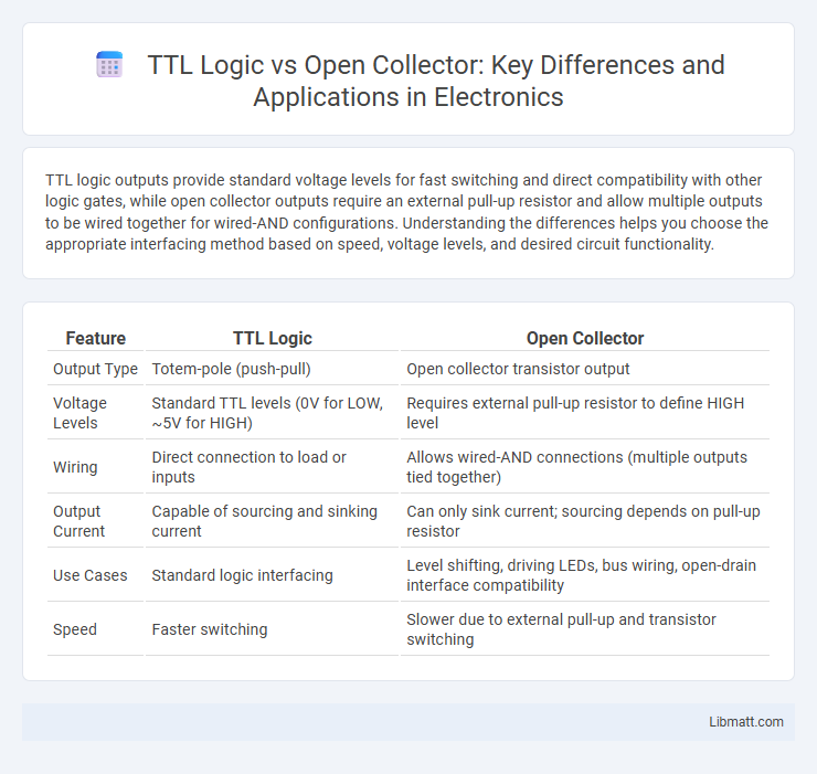
TTL logic outputs provide standard voltage levels for fast switching and direct compatibility with other logic gates, while open collector outputs require an external pull-up resistor and allow multiple outputs to be wired together for wired-AND configurations. Understanding the differences helps you choose the appropriate interfacing method based on speed, voltage levels, and desired circuit functionality.
Table of Comparison
| Feature | TTL Logic | Open Collector |
|---|---|---|
| Output Type | Totem-pole (push-pull) | Open collector transistor output |
| Voltage Levels | Standard TTL levels (0V for LOW, ~5V for HIGH) | Requires external pull-up resistor to define HIGH level |
| Wiring | Direct connection to load or inputs | Allows wired-AND connections (multiple outputs tied together) |
| Output Current | Capable of sourcing and sinking current | Can only sink current; sourcing depends on pull-up resistor |
| Use Cases | Standard logic interfacing | Level shifting, driving LEDs, bus wiring, open-drain interface compatibility |
| Speed | Faster switching | Slower due to external pull-up and transistor switching |
Introduction to TTL Logic and Open Collector
TTL logic, based on transistor-transistor logic technology, uses digital circuits to represent binary states with standard voltage levels, typically 0V for logic low and 5V for logic high. Open collector outputs, common in TTL devices, allow multiple outputs to be wired together to a single line, enabling wired-AND logic by using an external pull-up resistor to define the high state. You can enhance circuit flexibility by understanding that TTL logic provides intrinsic switching capabilities, while open collector interfaces offer interoperability and multi-device communication without signal conflict.
Basic Principles of TTL Logic
TTL logic relies on bipolar junction transistors (BJTs) to create fast-switching digital circuits operating at 5V, where input and output levels are defined by voltage thresholds for reliable binary signal interpretation. Open collector outputs use a transistor's collector terminal as an open switch, requiring an external pull-up resistor to establish the output voltage level, enabling wired-AND configurations for multiple outputs. TTL logic gates inherently provide actively driven high and low states, while open collector outputs only actively drive the low state and rely on external components to achieve a high level.
Understanding Open Collector Outputs
Open Collector outputs use a transistor to pull the line to ground, requiring an external pull-up resistor for proper voltage levels, enabling multiple outputs to share a bus without damage. TTL logic outputs actively drive both high and low states, providing faster switching times and stronger current capabilities. Understanding the open collector configuration allows for wired-AND logic implementations and level shifting, essential in mixed voltage systems.
Key Differences Between TTL and Open Collector
TTL logic outputs provide defined high and low voltage levels driven by internal transistors, ensuring fast switching and clear signal integrity, while open collector outputs rely on an external pull-up resistor to define the high state, allowing multiple outputs to be wired together for wired-AND functionality. TTL outputs source and sink current within specified limits, giving predictable output levels, whereas open collector outputs can only sink current, requiring an external voltage supply for high level realization. Your choice depends on circuit requirements such as bus sharing, level shifting, and noise tolerance, with TTL logic favored for speed and standard signaling, and open collector ideal for wired logic or interfacing with different voltage domains.
Electrical Characteristics Comparison
TTL logic outputs operate at a standard voltage of 5V with defined high and low voltage levels typically around 2.4V (minimum) for high and 0.4V (maximum) for low, offering fast switching speeds and low output impedance suitable for direct interfacing with digital circuits. Open collector outputs use a transistor to sink current and require an external pull-up resistor, resulting in slower rise times and typically open-drain behavior with variable voltage levels depending on the pull-up voltage. The key electrical difference lies in TTL providing actively driven output states versus open collector outputs allowing wired-AND configurations and flexible voltage levels limited by pull-up components.
Applications of TTL Logic Circuits
TTL logic circuits are widely used in digital systems for applications such as microprocessor interfaces, counters, and memory devices due to their fast switching speeds and high noise immunity. These circuits excel in environments requiring reliable logic level translation and precise timing control. Common uses include driving LED displays, implementing arithmetic operations, and creating control logic in embedded systems.
Use Cases for Open Collector Outputs
Open collector outputs are ideal for interfacing with different voltage levels and creating wired-AND logic in digital circuits, often used in applications such as driving LEDs, relays, and shared buses. They allow multiple devices to pull a line low without causing damage, making them suitable for open-drain communication and interrupt signaling. Your designs benefit from open collector outputs when you need flexible voltage interfacing or external pull-up resistors to ensure signal integrity in complex systems.
Advantages and Disadvantages of Each Approach
TTL logic offers fast switching speeds and simple interfacing with standard voltage levels, making it ideal for high-speed digital circuits. Open collector outputs provide flexible wiring options such as wired-AND configurations and level shifting but require external pull-up resistors, which can slow down signal transitions. You should consider TTL logic for speed-critical applications, whereas open collector is better suited for applications needing multiple outputs to share a line or interface with different voltage levels.
Interfacing TTL With Open Collector Devices
Interfacing TTL logic with open collector devices requires careful consideration of voltage levels and current sinking capabilities to ensure proper signal communication. Open collector outputs pull the line low by sinking current, while TTL inputs need a defined high logic level, often achieved using an external pull-up resistor to the supply voltage. Your circuit's reliability depends on selecting appropriate resistor values to maintain signal integrity and prevent damage during the TTL and open collector integration.
Selecting the Right Output Type for Your Circuit
Selecting the right output type for your circuit depends on speed, voltage compatibility, and load requirements; TTL logic outputs provide fast switching speeds and standard voltage levels ideal for direct digital interfacing. Open collector outputs allow multiple devices to share a single line through wired-AND configurations and can interface with different voltage levels via external pull-up resistors, offering flexibility in mixed-voltage systems. Consider TTL for high-speed, single-voltage applications, while open collector is preferable for bus-oriented designs and level shifting.
TTL logic vs Open collector Infographic