Ladder Diagrams use graphical symbols resembling electrical relay logic, making them ideal for programmers familiar with wiring and control circuits, while Function Block Diagrams represent control functions as blocks with inputs and outputs, facilitating modular design and easier reuse of code. You can choose based on your project needs: Ladder Diagrams for straightforward relay logic implementation or Function Block Diagrams for complex process control and signal processing tasks.
Table of Comparison
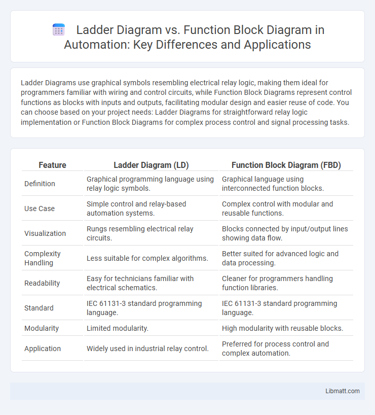
| Feature | Ladder Diagram (LD) | Function Block Diagram (FBD) |
|---|---|---|
| Definition | Graphical programming language using relay logic symbols. | Graphical language using interconnected function blocks. |
| Use Case | Simple control and relay-based automation systems. | Complex control with modular and reusable functions. |
| Visualization | Rungs resembling electrical relay circuits. | Blocks connected by input/output lines showing data flow. |
| Complexity Handling | Less suitable for complex algorithms. | Better suited for advanced logic and data processing. |
| Readability | Easy for technicians familiar with electrical schematics. | Cleaner for programmers handling function libraries. |
| Standard | IEC 61131-3 standard programming language. | IEC 61131-3 standard programming language. |
| Modularity | Limited modularity. | High modularity with reusable blocks. |
| Application | Widely used in industrial relay control. | Preferred for process control and complex automation. |
Introduction to Ladder Diagram and Function Block Diagram
Ladder Diagram (LD) is a graphical programming language resembling electrical relay logic, widely used for designing and documenting control logic in industrial automation systems. Function Block Diagram (FBD) employs interconnected function blocks that represent specific functions, making it ideal for complex process control and signal processing applications. Understanding the strengths of LD for straightforward relay logic and FBD for modular, reusable functions can help optimize Your PLC programming approach.
Overview of PLC Programming Languages
Ladder Diagram (LD) and Function Block Diagram (FBD) are two primary PLC programming languages used in industrial automation for controlling machinery and processes. Ladder Diagram, resembling electrical relay logic, uses graphical symbols to represent control circuits and is intuitive for technicians familiar with wiring diagrams, while Function Block Diagram employs pre-defined functional blocks interconnected to depict complex control functions and data flow. Your choice depends on application complexity and programmer expertise, with LD favored for straightforward sequential control and FBD suited for modular and reusable code structures.
Key Features of Ladder Diagrams
Ladder diagrams utilize a graphical representation resembling electrical relay logic, ideal for simple control circuits with clear on/off logic. They consist of rungs representing control logic, enabling easy debugging and straightforward programming for ladder logic controllers. Widely used in industrial automation, ladder diagrams excel in their simplicity and real-time monitoring capabilities.
Key Features of Function Block Diagrams
Function Block Diagrams (FBD) use graphical blocks to represent functions, making complex control systems easier to visualize and modify compared to Ladder Diagrams. Each block in FBD encapsulates specific operations, allowing for modular, reusable, and scalable programming suitable for advanced automation tasks. Your control logic benefits from clear data flow representation and improved troubleshooting through the interconnected function blocks.
Visual Representation and Syntax Comparison
Ladder Diagram (LD) uses a graphical representation resembling electrical relay logic with vertical rails and horizontal rungs, making it intuitive for those familiar with traditional control circuits. Function Block Diagram (FBD) employs interconnected blocks representing functions or operations, emphasizing modularity and reusability within automation processes. The syntax of LD revolves around contacts and coils arranged in a linear sequence, whereas FBD syntax centers on block inputs, outputs, and connections that define signal flow and functional relationships.
Application Areas: When to Use Each Diagram
Ladder Diagrams excel in representing simple relay logic systems and are widely used in industrial automation for motor control and straightforward sequential processes. Function Block Diagrams are better suited for complex control systems involving multiple data processing tasks, such as process control and batch operations in chemical or manufacturing plants. Choose Ladder Diagrams when working with discrete on/off control logic, while Function Block Diagrams are ideal for continuous variable control and integrating diverse functions within your automation system.
Ease of Learning and User Friendliness
Ladder Diagrams are generally easier to learn for beginners due to their resemblance to electrical relay logic, making them intuitive for those familiar with traditional wiring schematics. Function Block Diagrams offer a visual and modular approach, often preferred for complex systems, but may require more time to master because of their abstract blocks and connections. Your choice between the two should consider your background and the specific complexity of the control system you are working with.
Troubleshooting and Maintenance Considerations
Ladder Diagram (LD) offers straightforward visual representations resembling electrical relay logic, making it easier for technicians to troubleshoot faults by following familiar schematic patterns. Function Block Diagram (FBD) provides modular blocks that encapsulate complex functions, which can simplify maintenance by isolating issues within individual blocks but may require more advanced understanding of data flow and signal interactions. Your choice between LD and FBD can impact troubleshooting speed and maintenance efficiency depending on the complexity of the control system and the technical expertise of the maintenance team.
Performance and Flexibility Differences
Ladder Diagrams excel in performance due to their straightforward, relay logic-based design, allowing faster execution in simple control systems, whereas Function Block Diagrams offer greater flexibility with modular, reusable blocks that handle complex processes efficiently. Function Block Diagrams support advanced functions like data manipulation and communication protocols, making them suitable for scalable and multi-functional applications. Ladder Diagrams prioritize ease of troubleshooting and real-time control, beneficial in systems requiring quick response and simplicity.
Choosing the Right Programming Language for Your Project
Ladder Diagram (LD) and Function Block Diagram (FBD) serve distinct purposes in industrial automation programming, with LD excelling in simple, relay logic-like control systems and FBD better suited for complex process control requiring modularity and reusability. Selecting the right programming language depends on your project's complexity, scalability, and the engineers' familiarity; LD offers ease of troubleshooting for straightforward tasks, while FBD promotes clearer visualization for sophisticated data flow and control logic. Evaluate your system requirements and team expertise to optimize development efficiency and maintenance over the project lifecycle.
Ladder Diagram vs Function Block Diagram Infographic