A D flip-flop captures and stores a single bit of data on the clock edge, making it ideal for data storage and synchronization applications. JK flip-flops are more versatile, allowing toggling, setting, or resetting based on input combinations, which suits counters and more complex state machines in digital circuits.
Table of Comparison
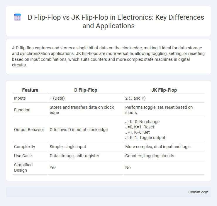
| Feature | D Flip-Flop | JK Flip-Flop |
|---|---|---|
| Inputs | 1 (Data) | 2 (J and K) |
| Function | Stores and transfers data on clock edge | Performs toggle, set, reset based on inputs |
| Output Behavior | Q follows D input at clock edge |
J=K=0: No change J=0, K=1: Reset J=1, K=0: Set J=K=1: Toggle output |
| Complexity | Simple, single input | More complex, dual input and logic |
| Use Case | Data storage, shift register | Counters, toggling circuits |
| Simplified Design | Yes | No |
Introduction to Flip-Flops
Flip-flops are fundamental bistable devices used in digital circuits to store binary information, with the D flip-flop and JK flip-flop being two primary types. The D flip-flop captures and stores the value of the data input at the moment of the clock edge, ensuring a straightforward and predictable single-bit storage. In contrast, the JK flip-flop functions as a versatile memory element with two inputs, capable of toggling, setting, or resetting states based on input combinations, making it suitable for more complex sequential logic designs.
Overview of D Flip-Flop
A D flip-flop is a digital memory circuit used to store a single bit of data, with a data input (D), a clock input, and outputs Q and Q'. The output Q follows the input D only at the triggering edge of the clock signal, ensuring synchronization in sequential circuits. It is widely used for data storage, data transfer, and latch operations in registers and counters.
Overview of JK Flip-Flop
The JK flip-flop is a versatile bistable multivibrator used in digital circuits for storage and toggling applications. It has two inputs, J and K, allowing it to perform set, reset, and toggle operations based on input combinations and clock signals. This flexibility makes the JK flip-flop suitable for counters, shift registers, and memory devices where precise control over output states is required.
Functional Differences: D vs. JK Flip-Flop
The D flip-flop captures the input value (D) on the clock edge and holds it until the next clock, functioning as a data storage element with a single input. The JK flip-flop, featuring two inputs (J and K), can perform set, reset, and toggle operations based on input combinations, offering greater versatility in sequential logic circuits. The toggle capability of the JK flip-flop allows it to serve as a frequency divider, unlike the D flip-flop which lacks this functionality.
Circuit Diagram Comparison
The D flip-flop circuit diagram features a single data input (D) and a clock signal, ensuring output follows the input at the clock edge, offering simplicity and ease of use for data storage. The JK flip-flop circuit includes two inputs, J and K, enabling more versatile functionality such as set, reset, and toggle operations controlled by the clock signal. Understanding the differences in circuit diagrams helps you select the right flip-flop for specific digital logic applications requiring either straightforward data latching or complex state control.
Truth Table Analysis
The D flip-flop truth table features a single data input (D) where the output Q directly follows D on the clock edge, resulting in Q = D and \(\bar{Q} = \bar{D}\). The JK flip-flop truth table includes two inputs, J and K, enabling more complex control: when J=K=0, Q retains its state; when J=0 and K=1, Q resets to 0; when J=1 and K=0, Q sets to 1; when J=K=1, Q toggles its state. This makes the JK flip-flop more versatile for applications requiring toggle functionality, compared to the simpler, data-latching behavior of the D flip-flop.
Applications of D Flip-Flop
D flip-flops are widely used in digital circuits for data storage, delay elements, and synchronization, playing a crucial role in registers, shift registers, and counters. These flip-flops capture the input data on the clock's rising edge, ensuring precise timing control in sequential logic designs. You can rely on D flip-flops in applications requiring stable data latching and robust timing management, such as frequency dividers and state machines.
Applications of JK Flip-Flop
JK flip-flops are widely used in applications requiring versatile and reliable binary counters, shift registers, and frequency dividers due to their ability to toggle states without race conditions. They serve as fundamental building blocks in digital circuits for memory storage, pulse generation, and timing signal synchronization. Your digital design projects benefit from the JK flip-flop's flexibility in implementing state machines and sequential logic systems.
Advantages and Disadvantages
D flip-flops offer simplicity and ease of use, making them ideal for data storage and synchronization tasks with minimal circuit complexity, but they lack the toggle functionality inherent in JK flip-flops. JK flip-flops provide versatile operation with set, reset, and toggle capabilities, suitable for counters and complex state machines, though they require more intricate feedback logic that can lead to increased power consumption and design complexity. Understanding these trade-offs allows you to select the appropriate flip-flop type based on your digital circuit requirements.
Choosing Between D and JK Flip-Flops
Choosing between D flip-flops and JK flip-flops depends on circuit complexity and functionality requirements. D flip-flops offer straightforward data storage with a single data input, ideal for simple registers and memory storage. JK flip-flops provide greater versatility with toggle capability and elimination of invalid states, making them suitable for counters and complex sequential logic.
D flip-flop vs JK flip-flop Infographic