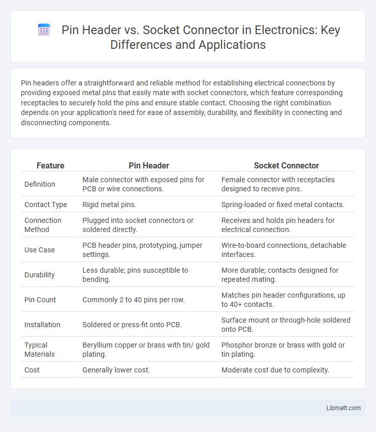
Pin headers offer a straightforward and reliable method for establishing electrical connections by providing exposed metal pins that easily mate with socket connectors, which feature corresponding receptacles to securely hold the pins and ensure stable contact. Choosing the right combination depends on your application's need for ease of assembly, durability, and flexibility in connecting and disconnecting components.
Table of Comparison
| Feature | Pin Header | Socket Connector |
|---|---|---|
| Definition | Male connector with exposed pins for PCB or wire connections. | Female connector with receptacles designed to receive pins. |
| Contact Type | Rigid metal pins. | Spring-loaded or fixed metal contacts. |
| Connection Method | Plugged into socket connectors or soldered directly. | Receives and holds pin headers for electrical connection. |
| Use Case | PCB header pins, prototyping, jumper settings. | Wire-to-board connections, detachable interfaces. |
| Durability | Less durable; pins susceptible to bending. | More durable; contacts designed for repeated mating. |
| Pin Count | Commonly 2 to 40 pins per row. | Matches pin header configurations, up to 40+ contacts. |
| Installation | Soldered or press-fit onto PCB. | Surface mount or through-hole soldered onto PCB. |
| Typical Materials | Beryllium copper or brass with tin/ gold plating. | Phosphor bronze or brass with gold or tin plating. |
| Cost | Generally lower cost. | Moderate cost due to complexity. |
Introduction to Pin Headers and Socket Connectors
Pin headers are male connectors consisting of rows of metal pins used to establish electrical connections on PCBs, enabling modularity and ease of assembly. Socket connectors are female components designed to receive pin headers, providing secure and reliable contact points for detachable connections in electronic devices. Both components are fundamental in electronics for flexible interfacing and efficient circuit design.
Key Differences Between Pin Headers and Socket Connectors
Pin headers are male connectors consisting of multiple exposed metal pins designed to insert into socket connectors. Socket connectors are female components featuring internal contacts that securely receive and hold pin headers for reliable electrical connections. The primary differences lie in their gender configuration, method of mating, and typical usage in printed circuit board (PCB) assemblies.
Construction and Design Features
Pin headers consist of rows of metal pins encased in a plastic base, designed for easy insertion into socket connectors or breadboards. Socket connectors feature corresponding receptacles or holes aligned to receive the pins, often incorporating spring-loaded contacts or metal clips to ensure secure electrical connections. Both components emphasize precise pin spacing, insulation materials, and mechanical durability to maintain reliable interfacing in electronic assemblies.
Electrical and Mechanical Performance
Pin headers typically provide reliable electrical conductivity with low contact resistance, ensuring consistent signal transmission. Socket connectors offer superior mechanical durability by protecting pins from physical damage and allowing easy insertion and removal, which is ideal for frequent connections. Your choice depends on balancing the need for strong electrical contact and resilient mechanical performance in your application.
Common Applications and Use Cases
Pin headers are extensively used in printed circuit board (PCB) interconnections for microcontroller programming, signal connections, and modular component attachments in electronics prototyping and development. Socket connectors serve critical roles in CPU chipset connections, memory modules, and plug-and-play device interfaces, providing reliable, removable connections for systems requiring frequent component swaps or upgrades. Both components are fundamental in embedded systems, industrial automation, and consumer electronics, where secure, compact, and versatile electrical connections are indispensable.
Advantages of Pin Headers
Pin headers offer a straightforward and cost-effective solution for establishing electrical connections in electronic assemblies, providing reliable mechanical stability and ease of integration onto printed circuit boards (PCBs). Their compact design allows high-density connections, making them ideal for space-constrained applications and enabling efficient signal transmission with minimal interference. You benefit from their versatility, as pin headers support a wide range of configurations and are compatible with various sockets, jumpers, and connectors for flexible system design.
Benefits of Socket Connectors
Socket connectors provide secure and reliable connections by allowing easy insertion and removal of pin headers without soldering, enhancing maintenance and upgrade flexibility. Their design minimizes the risk of damage to pins during repeated connections, increasing the lifespan of electronic components. Socket connectors also improve electrical stability and signal integrity, making them ideal for modular and prototyping applications.
Compatibility and Interfacing Considerations
Pin headers and socket connectors differ primarily in compatibility and interfacing, where pin headers provide sturdy male contact points, while socket connectors offer female receptacles to accommodate these pins. Your choice depends on board layout and mating requirements, ensuring proper alignment and secure electrical connections to prevent signal loss or damage. Compatibility considerations include pitch size, pin count, and mechanical durability to guarantee seamless integration within electronic assemblies.
Installation and Maintenance Tips
Pin headers require careful alignment during installation to prevent bent pins and ensure secure connections, while socket connectors often offer easier insertion with less risk of damage due to their receptacle design. Regular inspection of pin headers for corrosion or physical deformation is crucial, whereas socket connectors benefit from periodic cleaning to maintain reliable contact and prevent dust accumulation. Using appropriate tools, such as precision tweezers for pin headers and contact cleaners for sockets, can significantly extend the lifespan and performance of both connector types.
Choosing the Right Connector for Your Project
Choosing the right connector depends on factors such as ease of assembly, durability, and electrical performance; pin headers offer a straightforward connection ideal for prototyping, while socket connectors provide secure, removable interfaces suitable for frequent disconnects. Consider the current rating and pin pitch to ensure compatibility with your PCB design and avoid signal integrity issues. Selecting the appropriate connector type enhances connection reliability and simplifies maintenance in electronics projects.
Pin header vs Socket connector Infographic