Phase-Locked Loop (PLL) and Delay-Locked Loop (DLL) are both clock synchronization circuits used in electronics to align phases of signals; PLL uses a feedback system to adjust the frequency of a voltage-controlled oscillator, while DLL adjusts delay elements to match the input clock phase. You can choose a DLL for simpler, jitter-reduced synchronization, whereas PLLs are more versatile for frequency synthesis and tracking in communication systems.
Table of Comparison
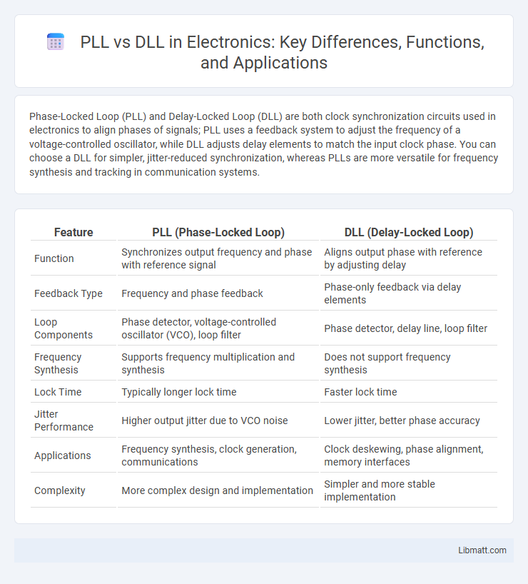
| Feature | PLL (Phase-Locked Loop) | DLL (Delay-Locked Loop) |
|---|---|---|
| Function | Synchronizes output frequency and phase with reference signal | Aligns output phase with reference by adjusting delay |
| Feedback Type | Frequency and phase feedback | Phase-only feedback via delay elements |
| Loop Components | Phase detector, voltage-controlled oscillator (VCO), loop filter | Phase detector, delay line, loop filter |
| Frequency Synthesis | Supports frequency multiplication and synthesis | Does not support frequency synthesis |
| Lock Time | Typically longer lock time | Faster lock time |
| Jitter Performance | Higher output jitter due to VCO noise | Lower jitter, better phase accuracy |
| Applications | Frequency synthesis, clock generation, communications | Clock deskewing, phase alignment, memory interfaces |
| Complexity | More complex design and implementation | Simpler and more stable implementation |
Understanding PLL and DLL: Definitions and Differences
Phase-Locked Loop (PLL) and Delay-Locked Loop (DLL) are essential circuits used for clock synchronization in digital systems. PLL synchronizes the output clock phase by continuously adjusting a voltage-controlled oscillator, while DLL aligns the clock by introducing controlled delay elements to match the reference clock phase. Unlike PLLs, DLLs provide more stable phase alignment with reduced jitter and no frequency synthesis, making them preferable in applications requiring precise timing control.
Core Principles of Phase-Locked Loops (PLL)
Phase-Locked Loops (PLLs) operate by synchronizing the output signal's phase and frequency with a reference input through a feedback loop comprising a phase detector, low-pass filter, and voltage-controlled oscillator. The phase detector compares the input and output phases, generating an error signal that adjusts the oscillator to minimize phase difference. This continuous phase alignment enables PLLs to maintain stable signal frequency and reduce jitter, making them essential in clock generation and synchronization applications.
Core Principles of Delay-Locked Loops (DLL)
Delay-Locked Loops (DLL) operate by comparing the phase of an input clock signal with a delayed version of itself to adjust timing delays precisely. Unlike Phase-Locked Loops (PLL), DLLs do not generate a new frequency but align the output clock phase to the reference clock by controlling delay elements. Your digital system can benefit from DLLs for reducing clock skew and jitter, enhancing synchronization accuracy in timing-critical applications.
Functional Architectures: PLL vs DLL
Phase-Locked Loops (PLL) utilize a voltage-controlled oscillator (VCO) combined with a phase detector and a low-pass filter to synchronize an output signal's phase and frequency with a reference input. Delay-Locked Loops (DLL) replace the VCO with a delay line controlled by a phase detector to adjust phase without changing frequency, effectively minimizing accumulated jitter. PLLs are suited for frequency synthesis and clock generation, while DLLs excel in precise phase alignment and clock distribution in digital circuits.
Key Applications of PLLs in Modern Electronics
PLLs (Phase-Locked Loops) are critical in modern electronics for frequency synthesis, clock generation, and signal synchronization in communication systems, microprocessors, and RF circuits. They enable precise timing control in applications such as wireless transceivers, data converters, and digital signal processing. Unlike DLLs (Delay-Locked Loops), PLLs can generate stable reference frequencies over a wide range, making them essential for complex systems requiring frequency modulation and phase alignment.
Typical Use Cases for DLLs
DLLs are primarily used in digital communication systems for clock data recovery and timing alignment, where precise phase adjustment without frequency changes is required. Your systems benefit from DLLs in applications such as jitter reduction in clock distribution networks and synchronization in high-speed data interfaces like DDR memory. These uses exploit DLLs' ability to generate stable timing signals with minimal phase error, enhancing signal integrity.
Performance Metrics: Jitter, Phase Noise, and Stability
Phase-Locked Loops (PLLs) typically exhibit higher jitter and phase noise compared to Delay-Locked Loops (DLLs) due to their reliance on voltage-controlled oscillators and feedback mechanisms. DLLs achieve lower jitter and improved stability by directly controlling delay elements, resulting in reduced phase noise and faster lock times. Stability in DLLs is generally superior as they avoid the accumulation of phase error over time, which is common in PLLs.
Design Challenges and Considerations
PLL (Phase-Locked Loop) design faces challenges such as managing loop stability, minimizing phase noise, and ensuring fast lock times, which require careful selection of loop filter components and voltage-controlled oscillator characteristics. DLL (Delay-Locked Loop) design considerations focus on delay element linearity, jitter performance, and matching delay to the reference clock period, with attention to process, voltage, and temperature variations to maintain timing accuracy. Your choice between PLL and DLL depends on the specific application constraints, including jitter tolerance and frequency multiplication needs.
Comparative Analysis: When to Use PLL or DLL
Phase-Locked Loops (PLL) excel in applications requiring frequency synthesis and clock generation with high-frequency multiplication, such as in communication systems and processors. Delay-Locked Loops (DLL) are preferred for clock synchronization and jitter reduction within integrated circuits, especially when precise phase alignment without frequency alteration is critical. Selecting between PLL and DLL depends on the specific need for frequency control versus phase adjustment, with PLLs offering dynamic frequency scaling and DLLs providing stable phase correction.
Future Trends in PLL and DLL Technologies
Future trends in PLL and DLL technologies emphasize higher integration with advanced semiconductor processes, enabling faster clock synchronization and reduced jitter in complex SoCs. Emerging applications demand PLLs and DLLs with ultra-low power consumption and enhanced adaptability to dynamic voltage and frequency scaling, improving your system's efficiency and reliability. Innovations in digital calibration and machine learning algorithms are poised to optimize phase alignment and minimize latency in next-generation communication and processing devices.
PLL vs DLL Infographic