An RLC circuit includes a resistor (R), inductor (L), and capacitor (C), offering resistance, inductance, and capacitance that affect the circuit's damping and resonance characteristics; an LC circuit contains only an inductor and capacitor, resulting in ideal oscillations with no energy loss. Your choice between these circuits depends on whether you need controlled energy dissipation (RLC) or pure oscillation for applications like filters, tuners, or oscillators (LC).
Table of Comparison
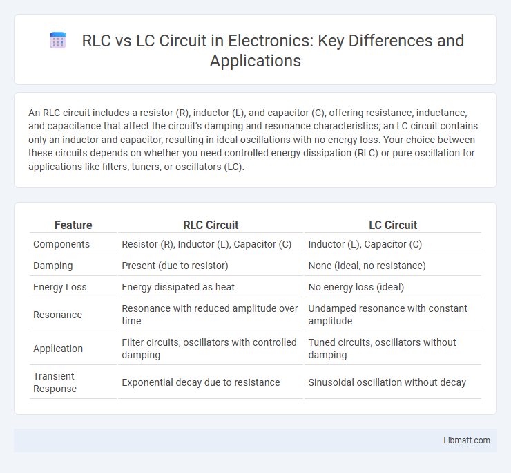
| Feature | RLC Circuit | LC Circuit |
|---|---|---|
| Components | Resistor (R), Inductor (L), Capacitor (C) | Inductor (L), Capacitor (C) |
| Damping | Present (due to resistor) | None (ideal, no resistance) |
| Energy Loss | Energy dissipated as heat | No energy loss (ideal) |
| Resonance | Resonance with reduced amplitude over time | Undamped resonance with constant amplitude |
| Application | Filter circuits, oscillators with controlled damping | Tuned circuits, oscillators without damping |
| Transient Response | Exponential decay due to resistance | Sinusoidal oscillation without decay |
Introduction to RLC and LC Circuits
RLC and LC circuits are fundamental components in electrical engineering, with LC circuits comprising inductors and capacitors that create resonant frequencies critical for tuning and filtering applications. RLC circuits include a resistor in series or parallel with the inductor and capacitor, introducing damping that affects the circuit's oscillation and transient response. The key difference lies in the resistor's impact on energy dissipation, where LC circuits idealize lossless resonance while RLC circuits model real-world scenarios with energy loss and phase shift.
Basic Components of LC and RLC Circuits
LC circuits consist of inductors (L) and capacitors (C) that store energy in magnetic and electric fields, respectively, enabling oscillations with minimal energy loss. RLC circuits include a resistor (R) along with the inductor and capacitor, introducing resistance that causes energy dissipation and affects the circuit's damping behavior. Understanding the basic components of these circuits helps you analyze resonance, frequency response, and energy transfer in electronic applications.
Resonance in LC vs RLC Circuits
Resonance in LC circuits occurs when the inductive reactance equals the capacitive reactance, causing the circuit to oscillate at its natural resonant frequency with minimal energy loss. In contrast, RLC circuits include resistance, resulting in a damped resonance where the peak amplitude is lower and the bandwidth is broader due to energy dissipation as heat. Understanding the impact of resistance helps you design circuits with desired resonance sharpness and stability for applications like filters and oscillators.
Differences in Circuit Behavior and Response
An RLC circuit contains resistors, inductors, and capacitors, influencing its damping and energy dissipation, while an LC circuit consists only of inductors and capacitors, exhibiting ideal oscillatory behavior with minimal energy loss. The presence of resistance in an RLC circuit causes exponential damping in the oscillations, leading to a gradual reduction in amplitude, whereas the LC circuit sustains continuous oscillations due to the absence of resistive elements. Frequency response in RLC circuits shows a broader bandwidth and lower resonance sharpness (Q factor) compared to the LC circuit's sharp resonance peak and narrower bandwidth.
Quality Factor: LC vs RLC Circuits
The quality factor (Q) of an LC circuit is generally higher than that of an RLC circuit because LC circuits ideally have no resistance, leading to minimal energy loss and sharper resonance. In contrast, the RLC circuit includes a resistor that introduces damping, reducing the Q factor and broadening the resonance peak. Your circuit's performance in filtering or tuning applications depends on balancing these quality factor differences to suit specific bandwidth and selectivity needs.
Damping in RLC Circuits: Absent in LC Circuits
RLC circuits exhibit damping due to the resistor, which dissipates energy and gradually reduces oscillations over time. In contrast, LC circuits lack this resistive element, resulting in undamped, continuous oscillations with constant amplitude. Understanding the presence of damping in your RLC circuit is crucial for designing systems that require controlled signal attenuation.
Applications of LC and RLC Circuits
LC circuits are widely used in radio frequency tuning, signal filtering, and oscillators due to their ability to select specific frequencies with minimal energy loss. RLC circuits find applications in audio equipment, impedance matching, and transient response control, where the resistor provides damping to stabilize oscillations and improve system performance. Both circuits are fundamental in wireless communication systems, with LC circuits enabling frequency selection and RLC circuits ensuring signal clarity and stability.
Energy Storage and Dissipation Comparison
RLC circuits combine resistors, inductors, and capacitors, allowing energy storage in inductors and capacitors while dissipating energy through resistors, unlike LC circuits that store energy without dissipation due to the absence of resistance. The inductor stores energy in its magnetic field, and the capacitor stores energy in its electric field, enabling oscillations with minimal energy loss in LC circuits. Understanding the energy storage and dissipation properties of RLC versus LC circuits helps optimize your designs for efficiency and signal fidelity.
Frequency Response and Selectivity
RLC circuits exhibit sharper frequency response and improved selectivity compared to LC circuits due to the presence of resistance, which introduces damping and controls bandwidth. The quality factor (Q) of an RLC circuit determines its selectivity, with higher Q values indicating narrower bandwidth and better frequency discrimination. In contrast, LC circuits typically have idealized, less controlled resonance peaks, resulting in lower selectivity under practical conditions.
Choosing Between LC and RLC Circuits
When choosing between LC and RLC circuits, consider that LC circuits consist solely of inductors and capacitors, providing ideal oscillation with no energy loss, making them suitable for frequency selection and filtering applications. RLC circuits include a resistor, introducing damping that controls oscillation amplitude and improves stability, which is essential for realistic signal processing where energy dissipation cannot be ignored. Your decision should be guided by whether you need pure resonance with minimal losses (LC) or controlled damping and bandwidth adjustment (RLC) for practical electronic designs.
RLC vs LC Circuit Infographic