Signal Integrity ensures that your electronic signals transmit without distortion or interference, maintaining waveform quality and timing accuracy across high-speed circuits. Power Integrity focuses on delivering stable and clean power throughout the system, minimizing voltage fluctuations and noise that can disrupt overall device performance.
Table of Comparison
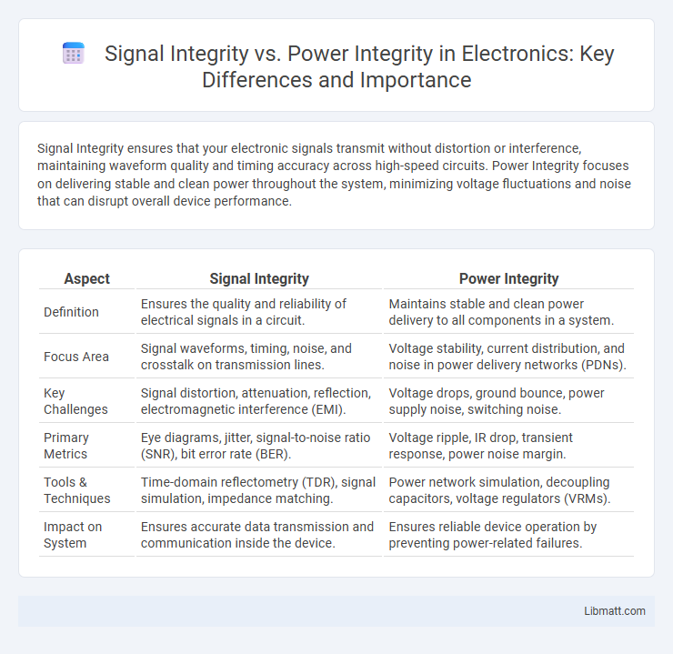
| Aspect | Signal Integrity | Power Integrity |
|---|---|---|
| Definition | Ensures the quality and reliability of electrical signals in a circuit. | Maintains stable and clean power delivery to all components in a system. |
| Focus Area | Signal waveforms, timing, noise, and crosstalk on transmission lines. | Voltage stability, current distribution, and noise in power delivery networks (PDNs). |
| Key Challenges | Signal distortion, attenuation, reflection, electromagnetic interference (EMI). | Voltage drops, ground bounce, power supply noise, switching noise. |
| Primary Metrics | Eye diagrams, jitter, signal-to-noise ratio (SNR), bit error rate (BER). | Voltage ripple, IR drop, transient response, power noise margin. |
| Tools & Techniques | Time-domain reflectometry (TDR), signal simulation, impedance matching. | Power network simulation, decoupling capacitors, voltage regulators (VRMs). |
| Impact on System | Ensures accurate data transmission and communication inside the device. | Ensures reliable device operation by preventing power-related failures. |
Introduction to Signal Integrity (SI) and Power Integrity (PI)
Signal Integrity (SI) ensures the quality and reliability of electrical signals by minimizing distortion, noise, and timing errors in high-speed digital circuits. Power Integrity (PI) focuses on maintaining stable and clean power delivery to integrated circuits, preventing voltage fluctuations and electromagnetic interference that can degrade system performance. Both SI and PI are critical in high-frequency PCB design to ensure optimal functionality and signal performance in advanced electronic systems.
Defining Signal Integrity: Key Concepts
Signal Integrity refers to the quality and reliability of electrical signals as they travel through a circuit, ensuring minimal distortion, noise, and timing errors. Key concepts include maintaining signal amplitude, controlling jitter, minimizing crosstalk, and preventing signal reflections through proper impedance matching and termination. Effective signal integrity is crucial for high-speed digital designs where data accuracy and timing precision directly impact system performance.
Understanding Power Integrity: Core Principles
Power integrity focuses on maintaining a stable voltage supply and minimizing noise and voltage fluctuations in electronic circuits to ensure reliable device performance. It involves managing the power delivery network, including decoupling capacitors, voltage regulators, and PCB layout to reduce impedance and prevent voltage drops. Understanding these core principles is essential to optimize your system's overall stability and prevent signal distortions caused by power-related noise.
Differences Between Signal Integrity and Power Integrity
Signal Integrity (SI) focuses on maintaining the quality and fidelity of electrical signals in high-speed digital circuits by minimizing noise, reflections, crosstalk, and timing errors. Power Integrity (PI) ensures a stable and clean power supply across the entire circuit by controlling voltage fluctuations, noise, and supply drop, which affects device performance and reliability. While SI addresses the accuracy of data transmission on interconnects and traces, PI targets the consistency of voltage delivery from the power source to active components.
Common Signal Integrity Challenges in PCB Design
Common signal integrity challenges in PCB design include crosstalk, reflection, and impedance mismatches that can degrade high-speed signal quality. Noise coupling and ground bounce further compromise signal clarity, requiring careful layer stacking and controlled impedance routing. Ensuring proper termination and minimizing signal path discontinuities are crucial for maintaining your PCB's overall performance.
Typical Power Integrity Issues in Modern Electronics
Typical power integrity issues in modern electronics include voltage fluctuations, ground bounce, and electromagnetic interference, which degrade system performance and reliability. Inadequate decoupling capacitor placement and poor power distribution network design cause transient voltage drops and increased noise, leading to signal distortion and operational errors. Effective mitigation involves optimized PCB layout, careful component selection, and robust power supply design to maintain stable voltage levels and minimize noise coupling.
The Interdependence of Signal and Power Integrity
Signal integrity (SI) and power integrity (PI) are fundamentally interdependent aspects of high-speed electronic design, where fluctuations in power delivery directly affect signal quality and timing. Noise on the power distribution network (PDN) can induce jitter and crosstalk in signal lines, while poor signal transitions can generate simultaneous switching noise that degrades power integrity. Effective design requires simultaneous optimization of both SI and PI parameters to minimize electromagnetic interference (EMI) and ensure reliable data communication across complex printed circuit boards (PCBs) and integrated circuits (ICs).
Tools and Techniques for Analyzing SI and PI
Signal integrity (SI) and power integrity (PI) rely on specialized tools and techniques for accurate analysis, including simulation software like SPICE-based circuit simulators, electromagnetic field solvers, and time-domain reflectometry (TDR). Techniques such as eye diagram analysis, impedance profiling, and decoupling capacitor modeling are crucial for assessing SI, while PI analysis emphasizes voltage drop analysis, power distribution network (PDN) impedance measurement, and transient current analysis. You can enhance your design robustness by employing these advanced tools and methods to identify and mitigate issues related to noise, voltage fluctuations, and signal distortion.
Best Practices for Optimizing Signal and Power Integrity
Maintaining signal integrity involves minimizing noise, crosstalk, and signal reflections through controlled impedance, proper termination, and careful PCB layout. Power integrity relies on stable voltage delivery achieved by using decoupling capacitors, low-inductance power planes, and robust power distribution networks. Your design will benefit from coordinated strategies that address both signal and power domains to ensure optimal performance and reliability.
Future Trends in Signal and Power Integrity
Emerging technologies like 5G, AI, and IoT are driving the need for advanced signal and power integrity solutions to handle higher frequencies and complex power delivery networks. Innovations in embedded capacitance, advanced materials, and real-time monitoring are improving the robustness of both signal integrity and power integrity in next-generation electronic designs. Your designs must adapt by integrating AI-driven diagnostics and predictive modeling to ensure reliable high-speed data transmission and stable power delivery in evolving electronic systems.
Signal Integrity vs Power Integrity Infographic