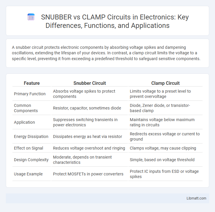
A snubber circuit protects electronic components by absorbing voltage spikes and dampening oscillations, extending the lifespan of your devices. In contrast, a clamp circuit limits the voltage to a specific level, preventing it from exceeding a predefined threshold to safeguard sensitive components.
Table of Comparison
| Feature | Snubber Circuit | Clamp Circuit |
|---|---|---|
| Primary Function | Absorbs voltage spikes to protect components | Limits voltage to a preset level to prevent overvoltage |
| Common Components | Resistor, capacitor, sometimes diode | Diode, Zener diode, or transistor-based clamp |
| Application | Suppresses switching transients in power electronics | Maintains voltage below maximum rating in circuits |
| Energy Dissipation | Dissipates energy as heat via resistor | Redirects excess voltage or current to ground |
| Effect on Signal | Reduces voltage overshoot and ringing | Clamps voltage, may cause clipping |
| Design Complexity | Moderate, depends on transient characteristics | Simple, based on voltage threshold |
| Usage Example | Protect MOSFETs in power converters | Protect IC inputs from ESD or voltage spikes |
Introduction to SNUBBER and CLAMP Circuits
Snubber circuits are designed to suppress voltage spikes caused by the rapid switching of inductive loads, protecting electronic components and enhancing circuit reliability. Clamp circuits limit voltage to a predetermined level by diverting excess voltage away from sensitive parts, preventing damage from transient overvoltages. Both circuits are critical in managing inductive switching transients but differ in operation, with snubbers focusing on energy dissipation and clamps on voltage limitation.
Fundamental Differences Between SNUBBER and CLAMP Circuits
Snubber circuits primarily protect semiconductor devices by absorbing voltage spikes and limiting voltage transients caused by inductive loads, utilizing components like resistors, capacitors, and sometimes diodes. Clamp circuits, on the other hand, restrict voltage to a predefined level by diverting excess voltage through elements such as zener diodes or avalanche diodes, thereby preventing voltage from exceeding critical thresholds. The fundamental difference lies in their operational focus: snubbers dissipate transient energy to smooth switching events, while clamps enforce voltage limits to safeguard circuits from overvoltage conditions.
Working Principle of SNUBBER Circuits
Snubber circuits protect electronic components by suppressing voltage spikes generated during rapid switching events in inductive loads. They work by absorbing and dissipating transient energy, typically using a resistor-capacitor (RC) or resistor-capacitor-diode (RCD) configuration to smooth voltage transitions. Understanding the working principle of snubber circuits helps you design safer, more reliable systems by preventing damage from voltage surges and reducing electromagnetic interference.
Working Principle of CLAMP Circuits
Clamp circuits operate by fixing the voltage level of an electrical signal to a predetermined reference point, effectively shifting the signal without altering its shape. They utilize components such as diodes, capacitors, and resistors to store and release charge, maintaining the output voltage at a desired DC level. This process protects sensitive electronic devices from voltage spikes and ensures signal integrity in various applications like pulse shaping and analog signal processing.
Key Components Used in SNUBBER Circuits
Snubber circuits primarily use resistors, capacitors, and sometimes diodes to suppress voltage spikes and limit transient currents in electronic circuits. The resistor-capacitor (RC) snubber is the most common configuration, where the resistor dissipates energy and the capacitor absorbs voltage surges. Your choice of these key components significantly affects the efficiency and protection level of the snubber circuit in safeguarding sensitive devices.
Key Components Used in CLAMP Circuits
Clamp circuits primarily use components such as diodes, resistors, and capacitors to maintain a fixed voltage level and protect sensitive electronic devices. The diode acts as the main element controlling the voltage clamping direction, while the resistor limits current flow and the capacitor stores charge to stabilize voltage fluctuations. Understanding these key components helps you design efficient clamp circuits to safeguard your electronic systems from voltage spikes.
Typical Applications of SNUBBER Circuits
Snubber circuits are commonly used in power electronics to protect semiconductor devices from voltage spikes caused by inductive loads during switching operations. They are essential in applications like motor drives, power supplies, and inverter circuits to suppress transient voltage and reduce electromagnetic interference. Snubbers enhance reliability and prolong device lifespan by controlling voltage overshoot and dissipating energy safely.
Typical Applications of CLAMP Circuits
Clamp circuits are widely used in signal processing to prevent voltage levels from exceeding a specified limit, protecting sensitive components from voltage spikes and transient disturbances. Typical applications include stabilizing AC signals to a fixed DC level, waveform shaping in analog circuits, and ensuring reliable digital signal levels in communication systems. Your electronic designs benefit from clamp circuits by maintaining signal integrity and enhancing component longevity.
Advantages and Limitations: SNUBBER vs CLAMP Circuits
Snubber circuits offer advantages such as efficient suppression of voltage spikes and improved protection of switching devices, but they often require careful component selection and can introduce power dissipation. Clamp circuits provide simple voltage limiting and fast response to transient voltages, benefiting from lower power loss, yet they may not suppress oscillations as effectively as snubbers. Both circuits play crucial roles in managing voltage transients, with snubbers excelling in energy absorption and clamps favoring straightforward voltage clamping.
Choosing the Right Circuit: SNUBBER or CLAMP?
Choosing between a snubber and clamp circuit depends primarily on the application requirements for voltage spike suppression and energy dissipation. Snubber circuits are ideal for controlling voltage spikes and reducing electromagnetic interference through energy absorption and controlled dissipation, often used with inductive loads and switching devices. Clamp circuits, on the other hand, are more suitable for limiting peak voltage to a safe level by redirecting excess energy, making them effective for protecting sensitive components from transient overvoltage conditions.
SNUBBER vs CLAMP Circuit Infographic