Edge connectors provide a simple and cost-effective way to connect printed circuit board (PCB) edges for reliable electrical signals, while board-to-board connectors offer versatile, high-density connections between two PCBs with various mating styles to fit complex designs. Choosing the right connector depends on Your device's space constraints, signal integrity requirements, and ease of assembly.
Table of Comparison
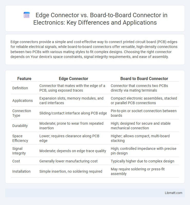
| Feature | Edge Connector | Board to Board Connector |
|---|---|---|
| Definition | Connector that mates with the edge of a PCB, using exposed traces | Connector that connects two PCBs directly via mating terminals |
| Applications | Expansion slots, memory modules, and card interfaces | Compact electronic assemblies, stacked or parallel PCB connections |
| Connection Type | Sliding/contact interface along PCB edge | Pin-to-pin or socket connection between boards |
| Durability | Moderate; prone to wear from repeated insertion | High; designed for secure and stable mechanical connection |
| Space Efficiency | Lower; requires clearance along PCB edge | Higher; allows compact, multi-board stacking |
| Signal Integrity | Moderate; depends on edge trace quality | High; controlled impedance with precise pin design |
| Cost | Generally lower manufacturing cost | Typically higher due to complex design |
| Installation | Simple insertion, no soldering required | May require soldering or press-fit assembly |
Introduction to Edge Connectors and Board to Board Connectors
Edge connectors provide a reliable interface by connecting directly to the edge of a printed circuit board (PCB), facilitating seamless integration with sockets or card slots in electronic devices. Board to board connectors enable electrical and mechanical connections between two separate PCBs, supporting high-density and high-speed signal transmission in complex electronic systems. Both connector types are essential in modular designs, with edge connectors often used for easy card insertion and removal, while board to board connectors prioritize compactness and multi-layer connectivity.
Key Differences Between Edge Connectors and Board to Board Connectors
Edge connectors feature a card-edge interface designed to plug directly into a mating socket, facilitating easy insertion and removal, whereas board to board connectors utilize paired male and female connectors mounted on separate PCBs for parallel or perpendicular stacking. Edge connectors typically offer simpler mechanical engagement and are common in applications like expansion cards, while board to board connectors provide higher pin density and more robust electrical pathways suited for complex multi-board systems. The key differences lie in their mating styles, mechanical stability, and application-specific design requirements.
Construction and Design Comparison
Edge connectors consist of a PCB edge that plugs into a mating socket, featuring gold-plated contacts embedded along the PCB's edge, allowing easy insertion and removal with minimal wear. Board-to-board connectors utilize pin-and-socket arrangements or mezzanine structures to enable stacked or parallel PCB connections, providing robust mechanical stability and higher pin density in compact form factors. The edge connector's design suits modular applications with frequent connect/disconnect cycles, while board-to-board connectors prioritize secure, high-reliability interconnections with versatile orientation options.
Electrical Performance and Signal Integrity
Edge connectors offer superior electrical performance by minimizing contact resistance and providing reliable, consistent connections for high-speed data transfer applications. Board-to-board connectors enhance signal integrity through robust mechanical alignment and multiple contact points, reducing crosstalk and electromagnetic interference (EMI). Both connector types are designed to maintain low insertion loss and controlled impedance, essential for preserving signal quality in demanding electronic systems.
Applications and Use Cases
Edge connectors are primarily used in applications requiring easy insertion and removal of printed circuit boards, such as in computer memory modules, graphics cards, and expansion cards, making them ideal for modular and upgradeable systems. Board to board connectors are preferred in high-density electronic assemblies like smartphones, medical devices, and industrial equipment where reliable, compact interconnection between PCBs is crucial for signal integrity and mechanical stability. Both types serve distinct roles: edge connectors excel in modular plug-in designs, while board to board connectors optimize space and performance in permanently assembled multi-board configurations.
Durability and Reliability Factors
Edge connectors offer superior durability due to their robust construction and resistance to wear from repeated mating cycles, making them ideal for high-reliability applications. Board-to-board connectors, while often more compact, may face challenges with mechanical stress and environmental exposure, potentially impacting long-term reliability. Choosing the right connector for your design ensures optimal durability and dependable electrical performance under varying operational conditions.
Installation and Maintenance Considerations
Edge connectors simplify installation by allowing circuit boards to slide directly into a mating socket, reducing assembly time and minimizing the need for soldering. Board-to-board connectors require precise alignment and soldering, increasing installation complexity and maintenance effort, but they offer more secure and compact interconnections. Your choice impacts maintenance accessibility, as edge connectors facilitate easier replacement, while board-to-board connectors may demand more disassembly and specialized tools for repairs.
Cost Comparison: Edge Connector vs Board to Board Connector
Edge connectors generally offer a lower cost solution compared to board-to-board connectors due to simpler manufacturing processes and reduced material usage. Board-to-board connectors, while typically more expensive, provide higher precision and reliability in complex multi-layer PCB assemblies. Cost efficiency for edge connectors is favored in high-volume, less complex applications, whereas board-to-board connectors justify their cost in performance-critical designs requiring robust signal integrity.
Industry Standards and Compatibility
Edge connectors follow strict industry standards such as PCIe, PCI, and ISA to ensure compatibility across various computer hardware and embedded systems, providing reliable signal integrity and mechanical stability. Board-to-board connectors adhere to standards like DIN 41612, MIL-DTL-83513, and Samtec's proprietary specs, enabling diverse stacking, mezzanine, and parallel board configurations for industrial and aerospace applications. Your selection between these connectors should consider the required standard compliance and physical board layout to ensure seamless integration and performance.
Choosing the Right Connector for Your Project
Selecting the right connector depends on the application's mechanical stability and signal requirements; edge connectors provide easy insertion and removal with reliable contact on PCB edges, ideal for modular designs and high-density applications. Board to board connectors offer stronger mechanical bonds and multi-directional connections suited for compact assemblies needing high current or data transfer rates. Evaluating electrical performance, mounting style, and environmental factors ensures optimal connectivity tailored to project specifications.
Edge Connector vs Board to Board Connector Infographic