An H-bridge inverter offers full control of the output waveform with the ability to reverse polarity, making it ideal for driving AC motors or bidirectional loads, while a half-bridge inverter provides a simpler, more cost-effective solution suitable for unidirectional power conversion. Choosing the right inverter depends on your requirements for output voltage control and complexity in motor or power applications.
Table of Comparison
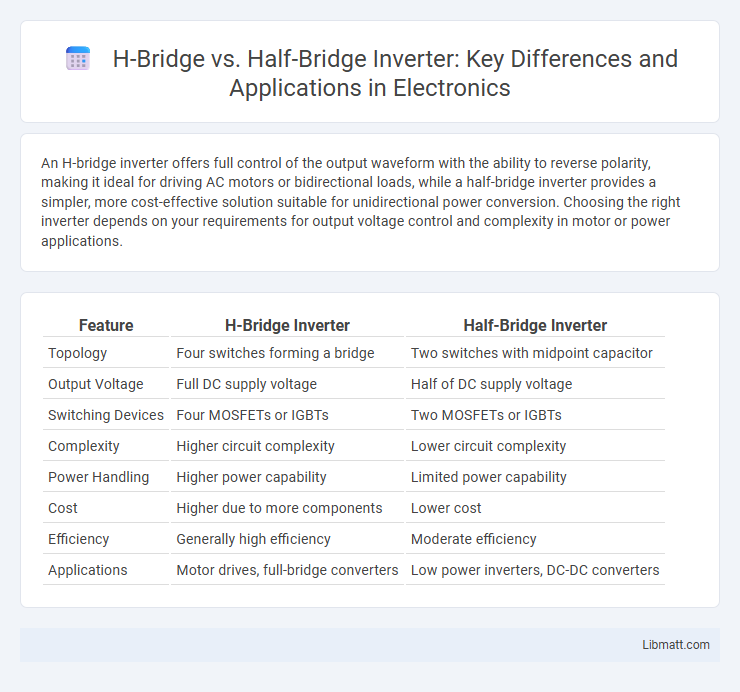
| Feature | H-Bridge Inverter | Half-Bridge Inverter |
|---|---|---|
| Topology | Four switches forming a bridge | Two switches with midpoint capacitor |
| Output Voltage | Full DC supply voltage | Half of DC supply voltage |
| Switching Devices | Four MOSFETs or IGBTs | Two MOSFETs or IGBTs |
| Complexity | Higher circuit complexity | Lower circuit complexity |
| Power Handling | Higher power capability | Limited power capability |
| Cost | Higher due to more components | Lower cost |
| Efficiency | Generally high efficiency | Moderate efficiency |
| Applications | Motor drives, full-bridge converters | Low power inverters, DC-DC converters |
Introduction to H-Bridge and Half-Bridge Inverters
H-bridge inverters consist of four switching devices arranged in an H-shaped configuration, enabling full DC-to-AC conversion with both positive and negative voltage outputs, making them ideal for bidirectional motor control and full waveform generation. Half-bridge inverters use two switching devices and two capacitors to split the DC supply voltage, producing a single-ended AC output with a voltage amplitude typically half the input DC voltage, suitable for low-power applications and simpler circuits. The fundamental difference lies in their switching topology and output voltage capabilities, influencing their efficiency and application scope in power electronics.
Working Principles of H-Bridge Inverters
H-bridge inverters operate by using four switches arranged in an H-like configuration to control the direction of current flow through the load, enabling the generation of a bipolar output voltage waveform. This topology allows for full-bridge operation, producing both positive and negative voltage pulses to efficiently convert DC into AC power. Your choice of an H-bridge inverter ensures precise control over output waveform quality, making it ideal for applications requiring bidirectional voltage and current flow.
Working Principles of Half-Bridge Inverters
Half-bridge inverters operate by switching two power transistors alternately, allowing voltage to be applied across the load in both directions while using a midpoint neutral point as a reference. This design enables efficient conversion of DC to AC power by dividing the DC supply into two equal halves, creating a balanced waveform with reduced voltage stress on components. Your choice of a half-bridge inverter supports applications requiring moderate power levels and simpler circuitry compared to the full H-bridge configuration.
Key Components and Circuit Topologies
H-bridge inverters consist of four switching devices arranged in an "H" configuration, enabling full voltage swing across the load and bidirectional current flow for efficient motor control. Half-bridge inverters use two switches and two capacitors, forming a midpoint voltage reference that provides only half the input voltage to the load, optimizing cost and complexity for lighter applications. Your choice between H-bridge and half-bridge topologies depends on the required power output, control precision, and application-specific voltage needs.
Voltage and Power Output Differences
H-bridge inverters provide a full DC voltage output by switching polarity, enabling them to deliver higher voltage and power compared to half-bridge inverters, which only generate half the DC voltage across the load. Due to this full voltage swing, H-bridge inverters are suited for applications requiring greater power density and efficiency, such as motor drives and uninterruptible power supplies (UPS). Half-bridge inverters are typically used in lower power applications or where cost and complexity need to be minimized, providing approximately half the power output capacity relative to H-bridge configurations.
Efficiency Comparison
H-bridge inverters typically exhibit higher efficiency than half-bridge inverters due to their ability to deliver full DC voltage to the load, minimizing conduction losses. Half-bridge inverters use two switches and split the DC voltage source, which can lead to increased switching losses and lower voltage utilization. Efficiency differences between the two topologies become more significant in high-power applications where voltage utilization and conduction losses critically impact overall performance.
Applications in Industry and Electronics
H-bridge inverters are widely used in electric motor control, robotics, and renewable energy systems due to their ability to provide bidirectional current flow and full voltage output, making them ideal for precise speed and torque control. Half-bridge inverters find applications in power supplies, audio amplifiers, and moderate power motor drives where cost efficiency and simplicity are prioritized over full voltage output. Your choice between H-bridge and half-bridge inverter depends on the specific industry requirements for power handling, control complexity, and application scale.
Advantages of H-Bridge Inverters
H-bridge inverters offer enhanced control over voltage polarity, enabling full-wave output and improved efficiency compared to half-bridge inverters. They provide better waveform quality with reduced harmonic distortion, making them ideal for driving inductive loads such as motors. The ability of H-bridge configurations to deliver higher output voltage levels increases power handling capacity in applications like renewable energy systems and electric vehicles.
Advantages of Half-Bridge Inverters
Half-bridge inverters offer a compact design with fewer components, resulting in lower cost and simpler circuit complexity compared to H-bridge inverters. Their ability to provide stable mid-point voltage makes them highly efficient for medium power applications, reducing harmonic distortion and enhancing output waveform quality. The reduced switching losses and ease of implementation in half-bridge topology improve overall system reliability and thermal management.
Limitations and Selection Criteria
H-bridge inverters offer full voltage output and bidirectional current flow but are limited by higher switching losses and complexity in control, making them less efficient for low-power applications. Half-bridge inverters provide a simpler design with reduced component count and lower cost, yet suffer from a limited voltage output and the need for a midpoint voltage reference, restricting their use in high-power scenarios. Your selection between these inverters should consider power requirements, efficiency needs, cost constraints, and the complexity of the control strategy.
H-bridge vs Half-bridge inverter Infographic