Snubber circuits protect electronic components by absorbing voltage spikes and limiting transient currents, whereas clamping circuits restrict voltage to a predefined level, preventing it from exceeding a safe threshold. Your choice depends on whether you need to manage energy dissipation during switching events (snubber) or enforce voltage limits to safeguard devices (clamping).
Table of Comparison
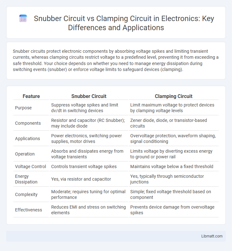
| Feature | Snubber Circuit | Clamping Circuit |
|---|---|---|
| Purpose | Suppress voltage spikes and limit dv/dt in switching devices | Limit maximum voltage to protect devices by clamping voltage levels |
| Components | Resistor and capacitor (RC Snubber); may include diode | Zener diode, diode, or transistor-based circuits |
| Applications | Power electronics, switching power supplies, motor drives | Overvoltage protection, waveform shaping, signal conditioning |
| Operation | Absorbs and dissipates energy from voltage transients | Limits voltage by diverting excess energy to ground or power rail |
| Voltage Control | Controls transient voltage spikes | Maintains voltage below a fixed threshold |
| Energy Dissipation | Yes, via resistor and capacitor | Yes, typically through semiconductor junctions |
| Complexity | Moderate; requires tuning for optimal performance | Simple; fixed voltage threshold based on component |
| Effectiveness | Reduces EMI and stress on switching elements | Prevents device damage from overvoltage spikes |
Introduction to Snubber and Clamping Circuits
Snubber circuits protect electronic components by absorbing voltage spikes and limiting transient voltages in power electronics, typically using resistors, capacitors, and sometimes diodes. Clamping circuits stabilize voltage levels by restricting the output voltage within a predetermined range, often employing diodes to prevent voltage from exceeding a specified threshold. Both circuits are essential for enhancing device reliability and preventing damage caused by voltage transients in switching applications.
Fundamental Concepts: What are Snubber Circuits?
Snubber circuits are protective electrical components designed to suppress voltage spikes and absorb transient energy in switching devices, preventing damage and improving device reliability. These circuits typically consist of resistors, capacitors, or diodes arranged to control rapid voltage changes during switching events. Understanding snubber circuits helps improve your power electronics system's efficiency and longevity by minimizing electrical noise and voltage stress.
Understanding Clamping Circuits
Clamping circuits are designed to fix the voltage level of a waveform to a desired DC value by adding a DC offset, typically using a diode, capacitor, and resistor. They protect sensitive electronics by preventing voltage from exceeding specified limits, ensuring signal integrity in communication and power systems. Unlike snubber circuits, which primarily suppress voltage spikes and dissipate transient energy, clamping circuits maintain voltage within a set range without significant energy dissipation.
Key Components and Operation Principles
A snubber circuit primarily uses resistors and capacitors to protect switching devices by absorbing voltage spikes and limiting the di/dt during switching transitions, thereby reducing electromagnetic interference and stress on components. In contrast, a clamping circuit generally employs diodes, zener diodes, or transistors to restrict the voltage to a predefined level, preventing overvoltage conditions and safeguarding your electronics. Understanding the key components and operation principles of these circuits enables you to choose the right protection method for your power electronics applications.
Purpose and Applications: Snubber Circuits
Snubber circuits primarily protect power semiconductor devices by suppressing voltage spikes and limiting transient currents during switching events, ensuring safe operation in inductive load environments. Commonly used in applications such as motor drives, power converters, and inductive load switching, snubbers enhance device longevity and system reliability. Their design typically involves resistors, capacitors, or diodes configured to absorb energy and reduce electromagnetic interference (EMI).
Purpose and Applications: Clamping Circuits
Clamping circuits are designed to fix or 'clamp' the voltage waveform to a desired DC level, protecting sensitive electronic devices from voltage spikes and ensuring signal integrity. Commonly used in signal processing and communication systems, clamping circuits stabilize output voltages for accurate data transmission and prevent damage in power supply units. Your electronic designs benefit from clamping circuits by maintaining voltage levels within safe operating ranges, enhancing overall device reliability.
Comparative Analysis: Snubber vs Clamping Circuits
Snubber circuits primarily protect switching devices by dissipating energy and controlling voltage spikes through resistors and capacitors, whereas clamping circuits limit voltage by redirecting excess energy using devices like diodes or zener diodes. Snubber circuits excel in reducing voltage overshoot and switching losses in inductive loads, while clamping circuits offer precise voltage regulation and fast response to transient spikes. The choice between snubber and clamping circuits depends on specific application needs such as energy dissipation efficiency, voltage stabilization requirements, and component complexity.
Advantages and Disadvantages of Each Circuit
Snubber circuits effectively suppress voltage spikes and reduce electromagnetic interference, but can introduce power losses and require careful component selection to avoid inefficiency. Clamping circuits offer precise voltage limiting to protect sensitive components from transient overvoltages, though they may cause increased stress on devices and are less effective against oscillations. Your choice depends on whether you prioritize energy dissipation and noise reduction (snubber) or strict voltage regulation and device protection (clamping).
Selection Criteria for Circuit Implementation
Selection criteria for implementing snubber or clamping circuits depend on the nature of voltage spikes and the specific protection needs of the electronic components. Snubber circuits are preferred for suppressing transient voltage spikes and reducing switching noise in inductive loads, often chosen for their capability to dissipate energy safely using resistors and capacitors. Clamping circuits are selected when limiting voltage to a specified threshold is critical, utilizing devices like Zener diodes or transistors to protect sensitive semiconductor components from overvoltage damage.
Conclusion: Choosing the Right Protection Circuit
Choosing the right protection circuit depends on the specific application requirements and circuit characteristics. Snubber circuits are ideal for controlling voltage spikes and dissipating energy in inductive loads, enhancing switch device reliability. Clamping circuits provide precise voltage limits to protect components from transient overvoltages, ensuring your devices operate within safe voltage ranges.
Snubber circuit vs Clamping circuit Infographic