An LC filter uses inductors and capacitors to achieve superior frequency selectivity and lower signal loss, making it ideal for radio frequency applications, while an RC filter relies on resistors and capacitors, offering simpler design and better performance at audio and low frequencies. Your choice depends on the specific application requirements, with LC filters preferred for high-frequency signals and RC filters for cost-effective, low-frequency filtering.
Table of Comparison
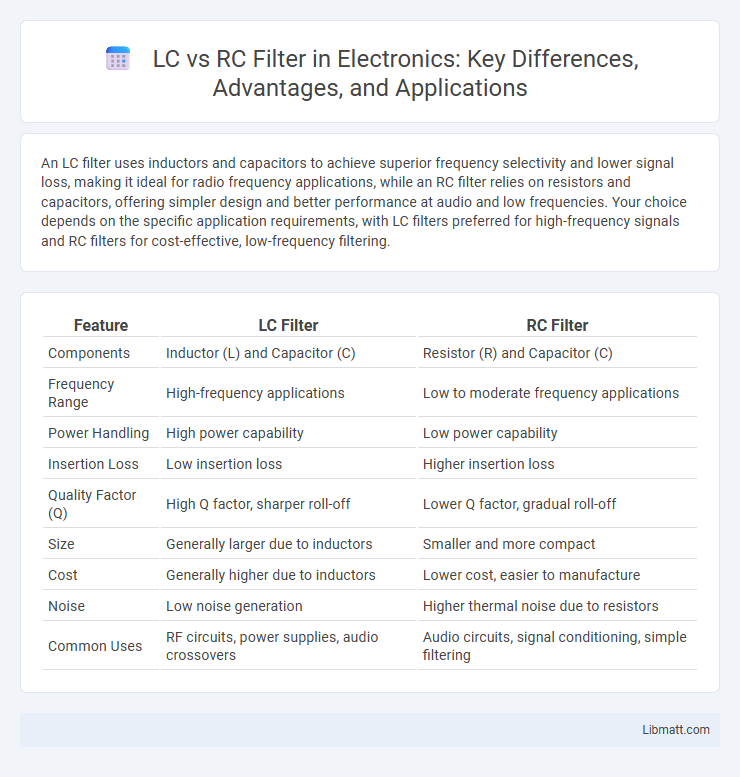
| Feature | LC Filter | RC Filter |
|---|---|---|
| Components | Inductor (L) and Capacitor (C) | Resistor (R) and Capacitor (C) |
| Frequency Range | High-frequency applications | Low to moderate frequency applications |
| Power Handling | High power capability | Low power capability |
| Insertion Loss | Low insertion loss | Higher insertion loss |
| Quality Factor (Q) | High Q factor, sharper roll-off | Lower Q factor, gradual roll-off |
| Size | Generally larger due to inductors | Smaller and more compact |
| Cost | Generally higher due to inductors | Lower cost, easier to manufacture |
| Noise | Low noise generation | Higher thermal noise due to resistors |
| Common Uses | RF circuits, power supplies, audio crossovers | Audio circuits, signal conditioning, simple filtering |
Introduction to LC and RC Filters
LC filters utilize inductors (L) and capacitors (C) to selectively allow frequencies to pass or be blocked, achieving sharper frequency response and lower signal loss than RC filters. RC filters, composed of resistors (R) and capacitors (C), are simpler and more cost-effective but offer less precise frequency cutoff and higher signal attenuation. Depending on Your signal conditioning needs, choosing between LC and RC filters influences filter performance in applications like audio processing, radio frequency tuning, and power supply noise reduction.
Basic Principles of LC Filters
LC filters utilize inductors (L) and capacitors (C) to achieve frequency selective filtering by exploiting the reactive properties of these components. The inductor resists changes in current while the capacitor resists changes in voltage, creating resonant circuits that allow certain frequency bands to pass while attenuating others. These filters offer higher quality factors (Q) and sharper cutoff slopes compared to RC filters, making them ideal for applications requiring precise frequency discrimination.
Basic Principles of RC Filters
RC filters utilize a resistor (R) and capacitor (C) to attenuate specific frequency components in electrical signals, based on the capacitor's reactance varying with frequency. In a low-pass RC filter, the capacitor blocks low-frequency signals less effectively and shunts high-frequency signals to ground, allowing low frequencies to pass. The cutoff frequency (f_c) is determined by the equation f_c = 1/(2pRC), defining the boundary between passed and attenuated frequencies.
Key Differences Between LC and RC Filters
LC filters utilize inductors and capacitors, offering superior frequency selectivity and lower power loss compared to RC filters, which rely on resistors and capacitors. LC filters are preferred in high-frequency applications due to their sharper cutoff and better performance in minimizing signal attenuation. RC filters are simpler, more cost-effective, and widely used in low-frequency circuits but suffer from higher power dissipation and less precise filtering capabilities.
Applications of LC Filters
LC filters are widely used in radio frequency (RF) communication systems to selectively pass desired signals while blocking unwanted frequencies, ensuring signal clarity and integrity. They play a crucial role in power supplies for smoothing output voltage and reducing noise, improving the overall performance of electronic circuits. You can find LC filters in audio equipment, wireless transmitters, and receivers, where precise frequency selection is essential for optimal operation.
Applications of RC Filters
RC filters are commonly used in audio processing to remove unwanted noise and shape frequency response in speakers and microphones. Your electronic circuits benefit from RC filters for signal smoothing and pulse shaping in analog-to-digital conversion. These filters are also essential in sensor signal conditioning to ensure accurate data acquisition in various measurement devices.
Performance Comparison: LC vs RC Filters
LC filters exhibit superior performance compared to RC filters due to their higher quality factor (Q-factor), enabling sharper cutoff frequencies and better selectivity in signal filtering applications. LC filters provide lower insertion loss and improved frequency response stability, making them ideal for high-frequency circuits, whereas RC filters show limitations at higher frequencies due to capacitor and resistor parasitic effects. The energy storage capability of inductors in LC filters also allows for more efficient filtering with less signal distortion compared to the purely resistive-capacitive structure of RC filters.
Design Considerations for LC and RC Filters
LC filters require precise selection of inductor and capacitor values to achieve desired frequency response, with attention to component quality factors and physical size constraints. RC filters offer simpler design and smaller form factors but face limitations in handling high power and achieving sharp cutoff frequencies. Your choice depends on balancing complexity, frequency accuracy, power handling, and physical size requirements.
Advantages and Limitations of Each Filter Type
LC filters offer high selectivity and low insertion loss, making them ideal for RF and high-frequency applications due to the energy storage properties of inductors and capacitors. However, their bulky size and susceptibility to electromagnetic interference limit their use in compact or noisy environments. RC filters provide simpler, more cost-effective designs with easier integration on printed circuit boards but suffer from higher power loss and less sharp cutoff characteristics compared to LC filters.
Choosing the Right Filter: LC or RC?
Choosing the right filter depends on the application requirements such as frequency range, quality factor, and power efficiency. LC filters offer superior performance at higher frequencies due to low power losses and high selectivity, making them ideal for radio frequency applications. RC filters provide simplicity, smaller size, and cost-effectiveness for low-frequency applications and signal conditioning where moderate filtering is sufficient.
LC vs RC filter Infographic