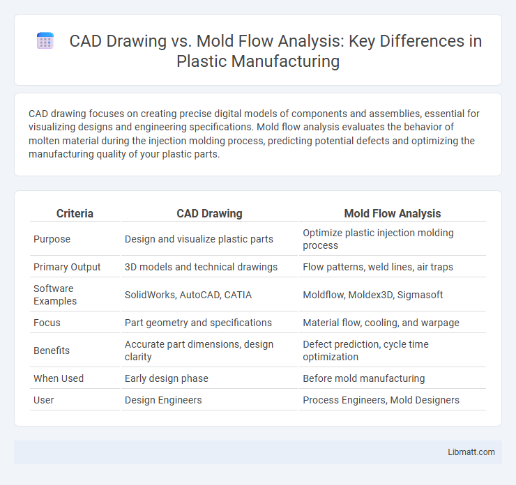
CAD drawing focuses on creating precise digital models of components and assemblies, essential for visualizing designs and engineering specifications. Mold flow analysis evaluates the behavior of molten material during the injection molding process, predicting potential defects and optimizing the manufacturing quality of your plastic parts.
Table of Comparison
| Criteria | CAD Drawing | Mold Flow Analysis |
|---|---|---|
| Purpose | Design and visualize plastic parts | Optimize plastic injection molding process |
| Primary Output | 3D models and technical drawings | Flow patterns, weld lines, air traps |
| Software Examples | SolidWorks, AutoCAD, CATIA | Moldflow, Moldex3D, Sigmasoft |
| Focus | Part geometry and specifications | Material flow, cooling, and warpage |
| Benefits | Accurate part dimensions, design clarity | Defect prediction, cycle time optimization |
| When Used | Early design phase | Before mold manufacturing |
| User | Design Engineers | Process Engineers, Mold Designers |
Introduction to CAD Drawing and Mold Flow Analysis
CAD drawing involves the creation of detailed 2D or 3D digital models used to design parts and assemblies with precision and accuracy, serving as the foundation for engineering and manufacturing processes. Mold flow analysis simulates the injection molding process to predict how molten plastic will fill a mold, identifying potential defects like air traps, weld lines, and sink marks before production. Understanding both CAD drawings and mold flow analysis helps optimize your product design for manufacturability and reduces costly revisions during the tooling phase.
Purpose and Importance in Manufacturing
CAD drawing serves as the foundational blueprint in manufacturing, detailing precise geometric designs and specifications essential for creating accurate molds and parts. Mold Flow Analysis evaluates the behavior of molten material during the injection molding process, identifying potential defects such as air traps, weld lines, and sink marks to optimize mold design and process parameters. Together, these tools enhance product quality, reduce production costs, and accelerate time-to-market by ensuring manufacturability and preventing costly errors.
Core Principles of CAD Drawing
CAD drawing utilizes precise digital tools to create detailed 2D or 3D representations of objects, emphasizing accuracy, dimensions, and geometric specifications essential for manufacturing and design validation. It forms the foundation for mold flow analysis by providing exact models that simulate material behavior during the injection molding process. Your design's success depends on the clarity and precision of CAD drawings to ensure seamless integration with subsequent mold flow simulations.
Key Features of Mold Flow Analysis
Mold flow analysis provides detailed simulation of plastic injection molding processes, enabling prediction of material flow, cooling patterns, and potential defects such as warpage or voids. It includes automated gating and runner design optimization, cycle time estimation, and identification of weld lines and air traps. These features help engineers enhance product quality and reduce manufacturing costs compared to traditional CAD drawing techniques.
Differences in Workflow and Application
CAD drawing involves creating detailed geometric designs and technical specifications for parts or molds, focusing on precise dimensions and shapes used for manufacturing. Mold flow analysis simulates the plastic injection molding process to predict potential defects, optimize material flow, and improve cooling efficiency, ensuring higher quality production outcomes. Your workflow shifts from pure design in CAD to simulation-driven decision-making in mold flow analysis, integrating both to enhance product performance and manufacturability.
Impact on Product Design Quality
CAD drawing enables precise visualization and detailed design modifications, ensuring high accuracy in product dimensions and features. Mold flow analysis predicts material behavior and potential defects during the injection molding process, optimizing the design for manufacturability and reducing risks of warping or sink marks. Integrating both enhances your product design quality by combining accurate design intent with validated manufacturing feasibility.
Error Detection and Troubleshooting
CAD drawing provides the detailed geometric blueprint essential for initial product design, but it lacks the capability to predict manufacturing defects. Mold flow analysis simulates plastic injection processes, enabling early detection of common errors such as air traps, weld lines, and sink marks. Using mold flow analysis alongside your CAD drawings enhances troubleshooting efficiency by identifying potential issues before physical prototyping.
Time and Cost Efficiency Comparison
CAD drawing streamlines the design phase by allowing rapid modifications and precise geometry creation, significantly reducing design time and costs. Mold flow analysis, while requiring initial investment in specialized software and expertise, prevents costly production errors by optimizing mold design and filling processes, saving time during manufacturing. Combining both ensures your project benefits from faster design cycles and minimized risk of expensive defects, enhancing overall cost efficiency.
Integration of CAD with Mold Flow Analysis
Seamless integration of CAD drawing with mold flow analysis enhances the precision of injection molding simulations by utilizing detailed design data directly from the CAD model. This integration enables rapid identification of potential defects such as air traps, weld lines, and sink marks, facilitating design optimization before manufacturing. Your ability to iterate quickly within the same digital environment reduces development time and improves overall product quality.
Choosing the Right Tool for Your Project
Selecting between CAD drawing and mold flow analysis depends on your project's stage and objectives; CAD drawing excels in creating precise 2D or 3D models essential for design visualization and modifications, while mold flow analysis provides critical insights into the injection molding process, predicting potential defects and optimizing material flow. For projects requiring early-stage design development and iteration, CAD tools offer efficient geometric accuracy, whereas mold flow analysis is indispensable for improving product quality and manufacturing efficiency by simulating real-world conditions. Understanding your project's needs ensures you leverage CAD for structural design and mold flow analysis for process validation and optimization.
CAD Drawing vs Mold Flow Analysis Infographic